23
Routine Service
Outboard Rigging Connections
2
SystemCheck Harness
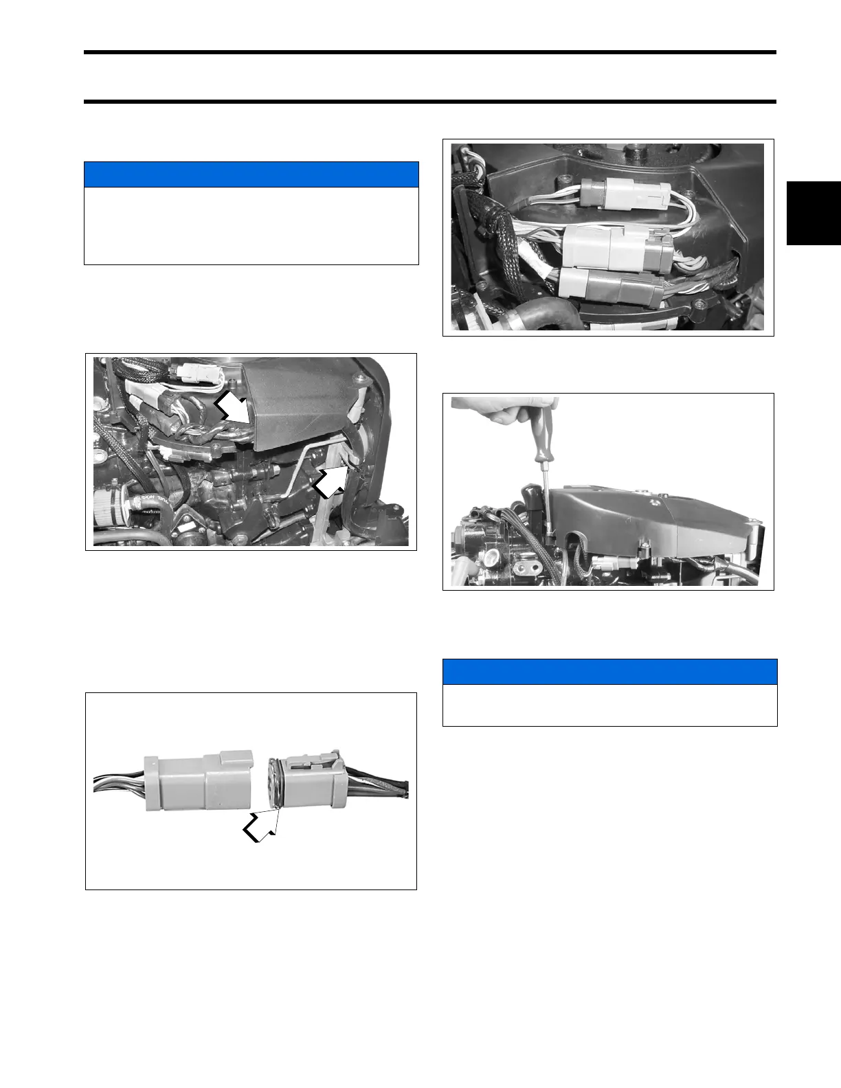
Connections
Place the wiring harness through notch in lower
motor cover and route to the recess in the fly-
wheel cover. Secure the cable with a tie strap as
shown:
Before installing electrical connectors, check that
the seal is in place. Clean off any dirt from con-
nectors. Apply a light coat of Electrical Grease to
the seal only. DO NOT fill connectors with Electri-
cal Grease.
Arrange connectors in flywheel cover.
Install electrical cover and secure with screws.
I-Command Network Connections
If the outboard will be used with I-Command, or
other NMEA 2000 compliant CANbus instruments,
use the following connections to supply informa-
tion to the network:
Remove lower motor covers. Remove air silencer.
Route I-Command Engine Interface Cable around
the front of the throttle body, following the path of
NOTICE
BE SURE all harnesses and wires are not
pinched, cannot contact flywheel, and do not
interfere with moving throttle or shift link-
ages.
1. Recess
2. Tie strap
002011
1. Seal
42079A
001999
002102
NOTICE
To prevent wire chafing, harness must be
routed below the flywheel cover.