25
Routine Service
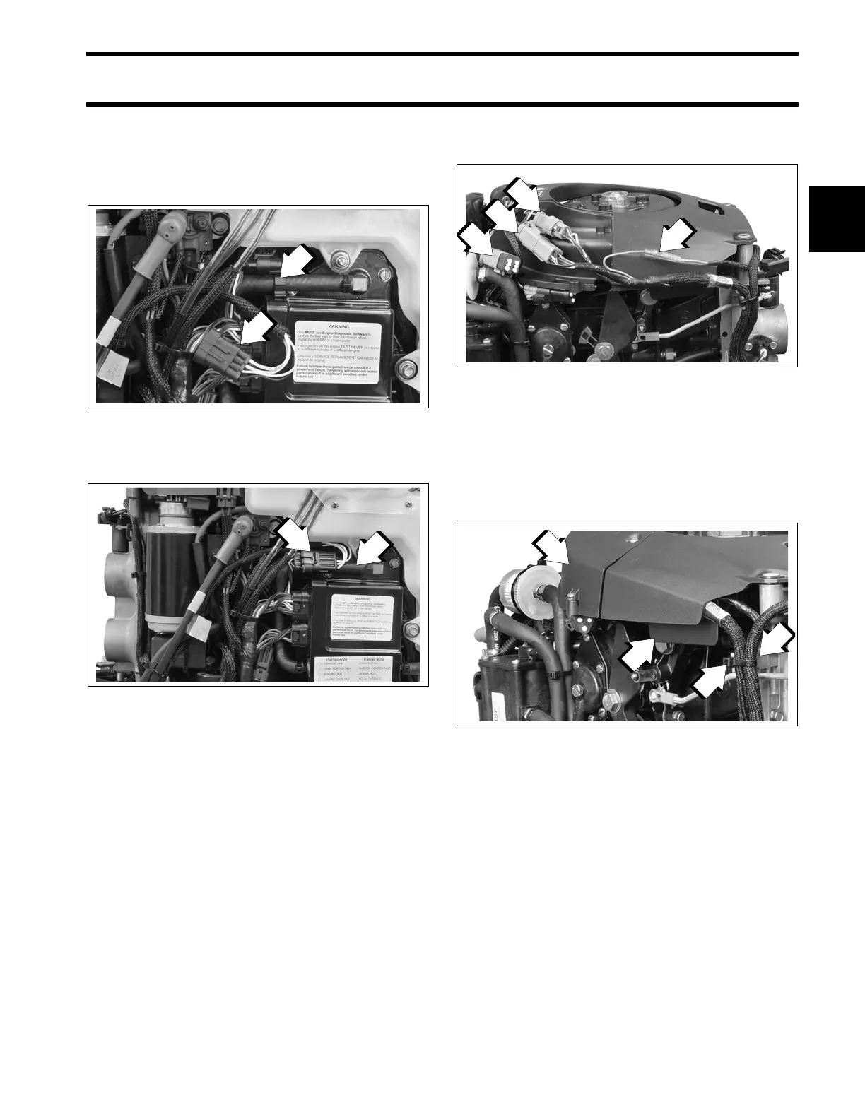
Outboard Rigging Connections
2
3 Cylinder Models
EMM CANbus connector cap is clipped to EMM
cooling water hose. Remove clip from cap and
install on I-Command harness connector.
Install clip and connector to hose.
All Models
Adjust harness routing as needed and secure with
tie straps.
Use an I-Command Ignition and Trim Harness to
connect the outboard to the key switch and trim/tilt
control. Seal unused SystemCheck connector
with 6-Pin Connector Seal, P/N 586076.
If connecting to an existing I-Command Classic
network, connect the purple wires between the I-
Command Ignition and Trim Harness and the I-
Command Engine Interface Cable. This connec-
tion supplies power to the network when the key
switch is on. I-Command Digital networks do not
use this connection.
Route I-Command Ignition Harness through wire
channel in flywheel cover. Install electrical cover.
Make sure both harnesses are in front of the tab
and tighten with tie strap.
1. Canbus harness connector
2. EMM CANbus connector clip
006743
1. CANbus connectors
2. EMM cooling water hose
006744
1. Trim/Tilt connector
2. CANbus Ignition connector
3. SystemCheck connector (with seal)
4. Bullet-style harness power connector
006734
1. Electrical cover
2. Wire channel
3. Tab
4. Tie strap
006737