100
ELECTRICAL AND IGNITION
SENSOR TESTS
Connect red meter lead to terminal “A” and black
meter lead to terminal “C.” Rotate the sensor lever
through its range of travel. Resistance reading
must change evenly as the sensor lever is moved.
Connect red meter lead on terminal “B” and black
meter lead to terminal “C.” Rotate the sensor
lever. Resistance reading must change evenly as
the sensor lever is moved.
Engine Temperature Sensor Test
Remove the electrical connector from the engine
temperature sensor.
Use a digital multimeter to measure sensor resis-
tance.
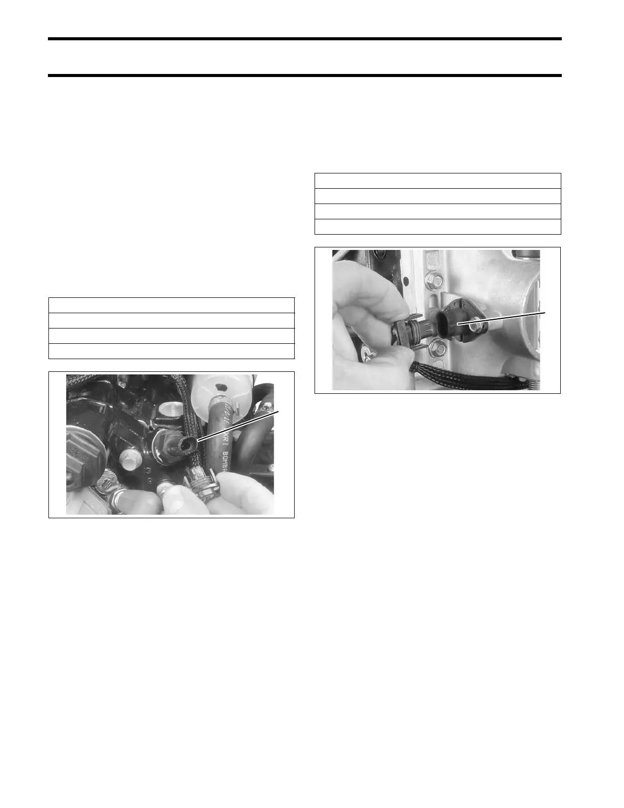
Air Temperature Sensor (AT) Test
Remove the electrical connector from the air tem-
perature sensor.
Use a digital multimeter to measure sensor resis-
tance.
Engine Temperature Sensor Resistance
680 Ω ± 5% @ 212°F (100°C)
10000 Ω ± 1% @ 77°F (25°C)
32654 Ω ± 2.5% @ 32°F (0°C)
1. Engine temperature sensor 006612
AT Sensor Resistance
680 Ω ± 5.25% @ 212°F (100°C)
10000 Ω ± 1.5% @ 77°F (25°C)
32654 Ω ± 3.0% @ 32°F (0°C)
1. AT sensor 006613