198
POWERHEAD
POWERHEAD DISASSEMBLY
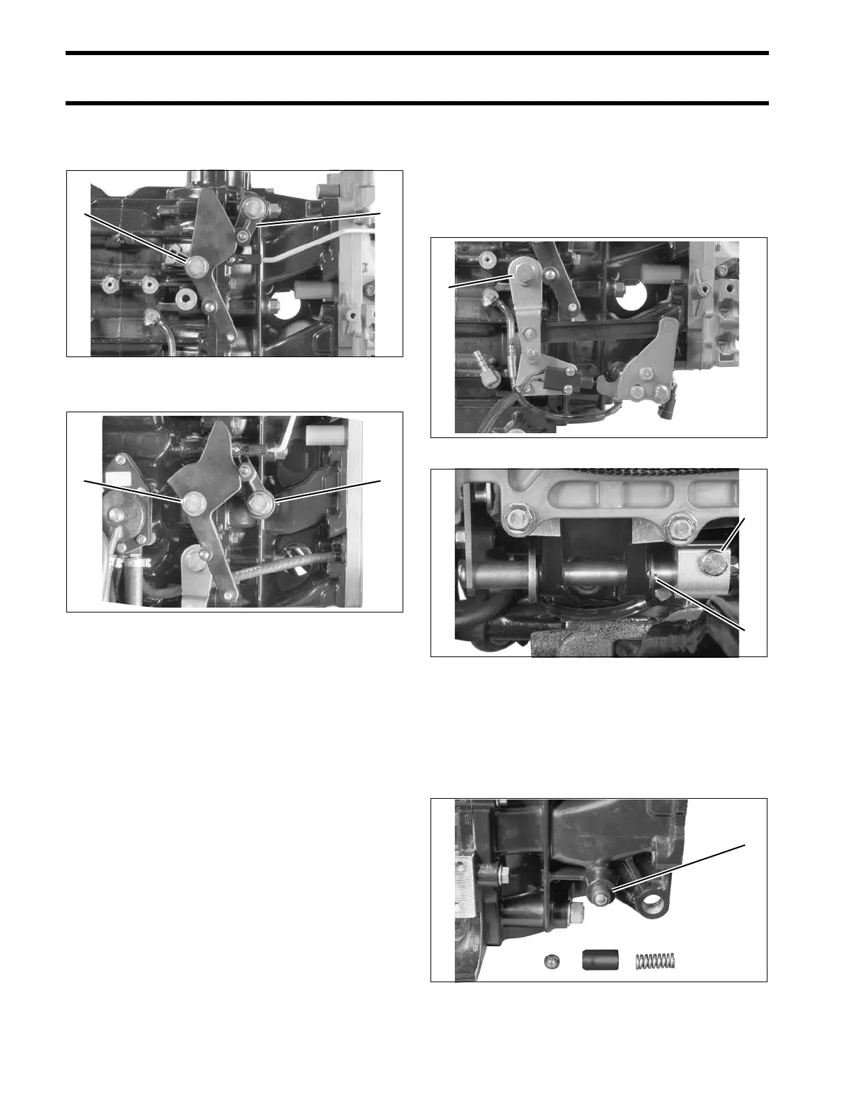
Throttle Linkage Removal
Remove throttle cam and throttle lever.
Shift Linkage Removal
Remove shoulder screw from shift arm and retain-
ing screw from shift rod lever.
Remove the cotter pin and washer holding the
shift shaft (2-cylinder models).
Slide entire shift linkage assembly from crank-
case.
Remove the ball, guide, and spring of the shift
detent assembly from the crankcase.
2-Cylinder Models
1. Throttle lever screw
2. Throttle return lever
002245
3-Cylinder Models
1. Throttle cam screw
2. Throttle lever screw
002257
1. Shift lever screw 002250
1. Shift rod lever screw
2. Cotter pin
002246
1. Shift detent assembly 002135