23
ROUTINE SERVICE
OUTBOARD RIGGING CONNECTIONS
2
After installation, make sure there
is enough clearance for all cables to avoid
binding or chafing through all engine steering
and tilting angles.
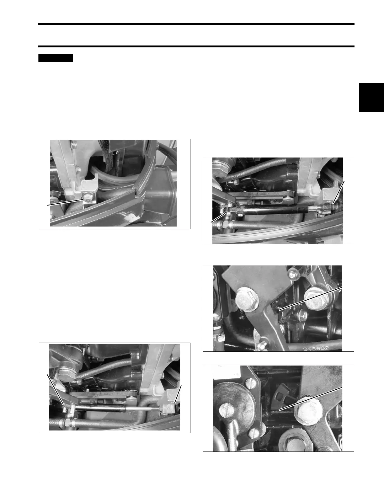
Control Cable Installation
Refer to Control Cable Identification on p. 21.
Remove cable retainer from anchor block. Apply
Triple-Guard grease to both anchor block pockets.
IMPORTANT: DO NOT secure cables to throttle
and shift lever pins until all cables, wires, and
hoses have been routed and grommet has been
installed in the lower engine cover.
Make sure the remote control is in NEUTRAL, and
throttle is in the IDLE position.
Pull firmly on shift cable casing to remove slack.
With outboard in NEUTRAL, place the cable trun-
nion into the lower anchor pocket. Adjust the trun-
nion nut so the casing fits onto the shift lever pin.
If there are not enough threads on the shift cable
for the adjustment, or if the gearcase does not
shift fully into FORWARD or REVERSE, refer to
SHIFT ROD ADJUSTMENT on p. 296, or SHIFT
ROD ADJUSTMENT on p. 319.
With remote control lever in NEUTRAL, pull firmly
on throttle cable casing to remove slack.
With engine throttle lever against stop, place the
cable trunnion into the upper anchor pocket and
adjust the trunnion nut so the casing fits onto the
throttle lever pin.
1. Cable retainer 002099
1. Shift lever pin
2. Trunnion nut
002100
1. Throttle lever pin
2. Trunnion nut
002101
1. Throttle lever stop – 3 Cylinder models 005111
1. Throttle lever stop – 2 Cylinder models 005114