EasyManuals Logo

BRP EVINRUDE E-TEC E90DSLAA Series User Manual

BRP EVINRUDE E-TEC E90DSLAA Series
422 pages
To Next Page IconTo Next Page
To Previous Page IconTo Previous Page
Page #59 background imageLoading...
Page #59 background image
59
ENGINE MANAGEMENT MODULE (EMM)
EMM INPUTS AND OUTPUTS DIAGRAM
4
EMM INPUTS AND OUTPUTS DIAGRAM
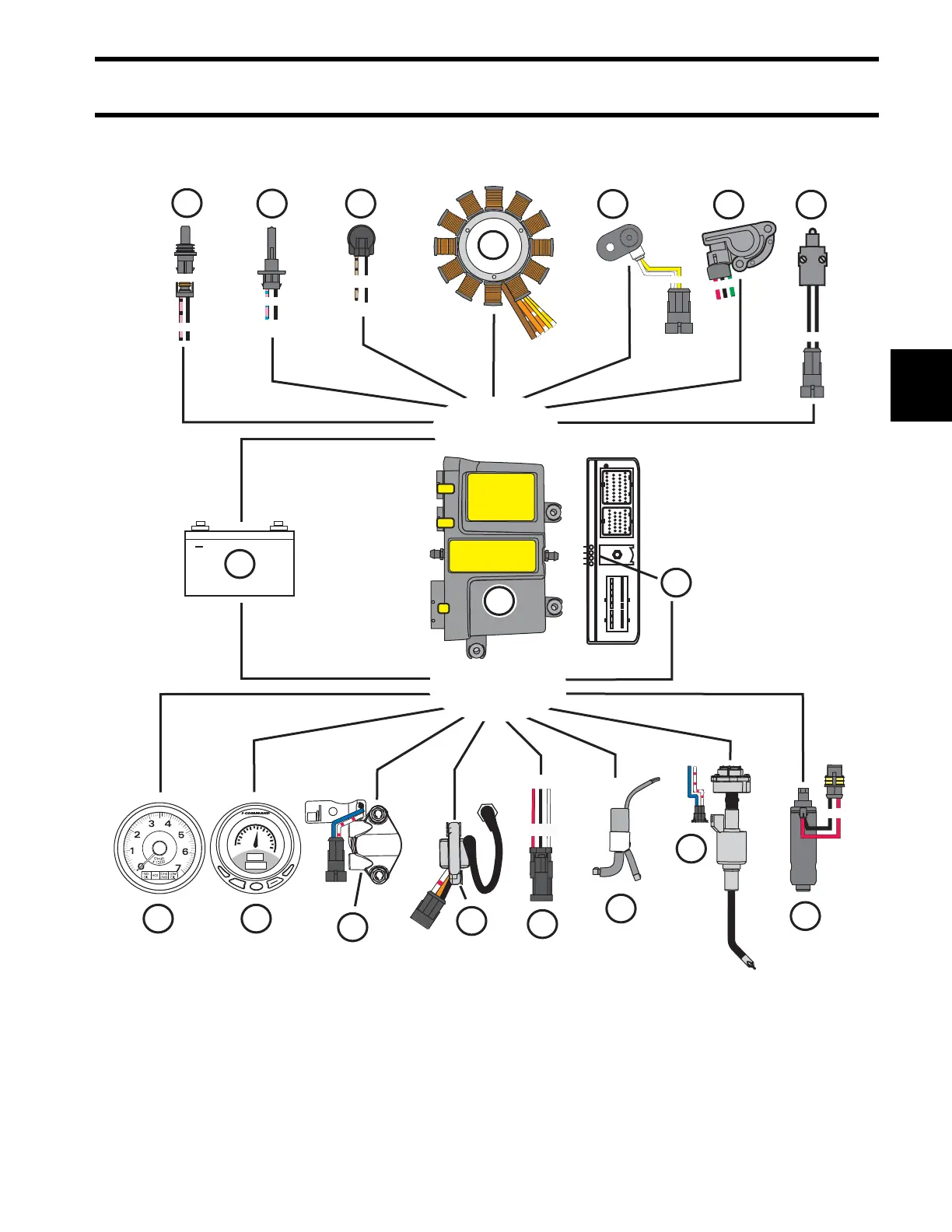
1. Engine Management Module (EMM)
2. Battery (12 volt)
3. Stator
4. Crankshaft Position Sensor (CPS)
5. Throttle Position Sensor (TPS)
6. Neutral Switch
7. Low Oil Switch
8. Air Temperature Sensor (AT)
9. Engine Temperature Sensor
10. Fuel Pump (high pressure)
11. Oil Injection Pump and Manifold
12. Ignition Coil
13. Fuel Injector
14. Tachometer/SystemCheck Gauge
15. I-Command (CANbus) Display
16. Diagnostic Connector
17. LED Indicators
18. Exhaust Water Valve (60–65 HP)
+
2
CB
A
INPUTS
OUTPUTS
A
B
12
1
21
J1-B
J1-A
J2
2
1
1
2
3
4
C
B
A
A B
MENU
DOWN
UP
EXIT
PAGES
ENTER
30
20
10
0
40
50
60
70
x 100
RPM
3550
12
1
2
3
4
5 6
78
9
10
11
13
14 15
16
17
18
008026

Table of Contents

Questions and Answers:

Question and Answer IconNeed help?

Do you have a question about the BRP EVINRUDE E-TEC E90DSLAA Series and is the answer not in the manual?

BRP EVINRUDE E-TEC E90DSLAA Series Specifications

General IconGeneral
BrandBRP
ModelEVINRUDE E-TEC E90DSLAA Series
CategoryEngine
LanguageEnglish

Related product manuals