OILING SYSTEM
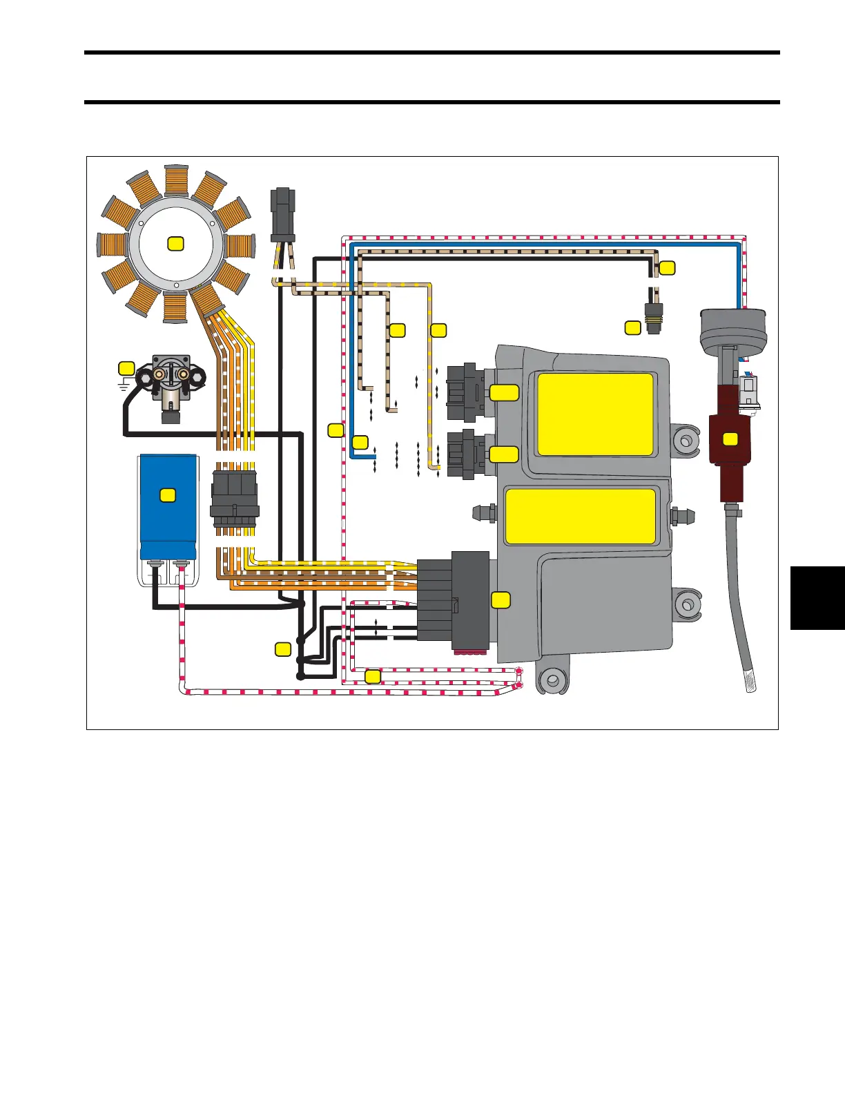
OILING SYSTEM CIRCUIT DIAGRAM
163
8
OILING SYSTEM CIRCUIT DIAGRAM
1.
2.
3.
4.
5.
6.
7.
8.
9.
10.
11.
12.
Stator
Main harness ground (BLACK)
Alternator grounds (BLACK)
Alternator output, WHITE / RED wires (55 V)
Capacitor (55 V)
EMM injector control (BLUE)
55 V to injection pump (WHITE / RED)
Oil injection pump
Low oil switch
Low oil switch to EMM (TAN/BLACK)
Low oil signal to SystemCheck gauge (TAN/BLACK)
No oil signal to SystemCheck gauge (TAN/YELLOW)
1
2
3
5
6
7
8
12
13
14
15
16
9
10
11
13
12
11
10
9
8
7
6
5
4
3
2
1
8
9
18
17
16
15
14
13
12
11
10
13
12
11
10
17
16
15
14
34
33
32
31
30
29
28
27
26
24
25
23
22
21
20
19
18
26
24
25
23
22
21
20
19
17
16
15
14
18
J1-B
J1-A
J2
4
1
23456
234561
345
7
6
4
3
2
1
5
1
9
12
2
7
5
8
AB
AB
3
4
6
10
11