216
POWERHEAD
POWERHEAD ASSEMBLY
Start in the center and work outward in a spiral
pattern.
Apply Nut Lock to crankcase flange screws. Install
screws and tighten to a torque of 60 to 84 in. lbs.
(7 to 9.5 N·m).
Test that the crankshaft spins freely without bind-
ing.
IMPORTANT: After powerhead has been
assembled, allow at least two hours for Gel-Seal II
to cure before running outboard.
Apply Gasket Sealing Compound to both sides of
a new water cover gasket. Place gasket and cover
on cylinder block.
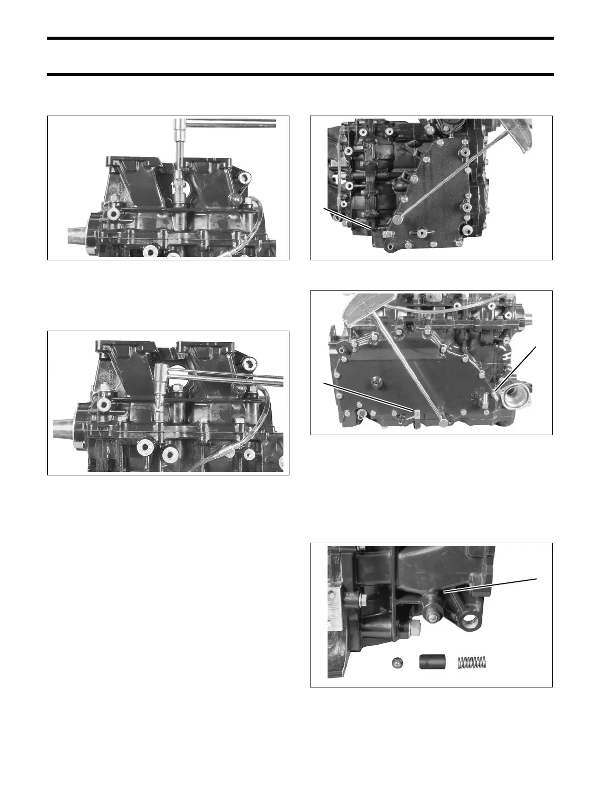
Apply Nut Lock to cover screws. Position J-
clamps as shown. Tighten all screws to a torque of
60 to 84 in. lbs. (7 to 9.5 N·m).
Note: 3-Cylinder models include a double-ended
stud and use a lock washer under the J-clamp.
Shift Linkage Installation
Place the spring, guide, and ball of the shift detent
assembly into the crankcase. Lubricate with Tri-
ple-Guard grease.
002254
002259
2-Cylinder models
1. J-clamp
002242r
3-Cylinder models
1. Double-ended stud
2. J-clamp
002122
1. Shift detent assembly 002135