222
POWERHEAD
POWERHEAD INSTALLATION
TION on p. 371.
Install the lower engine covers. Refer to LOWER
COVER SERVICE on p. 54.
Powerhead Mounting – 3-Cylinder
Models
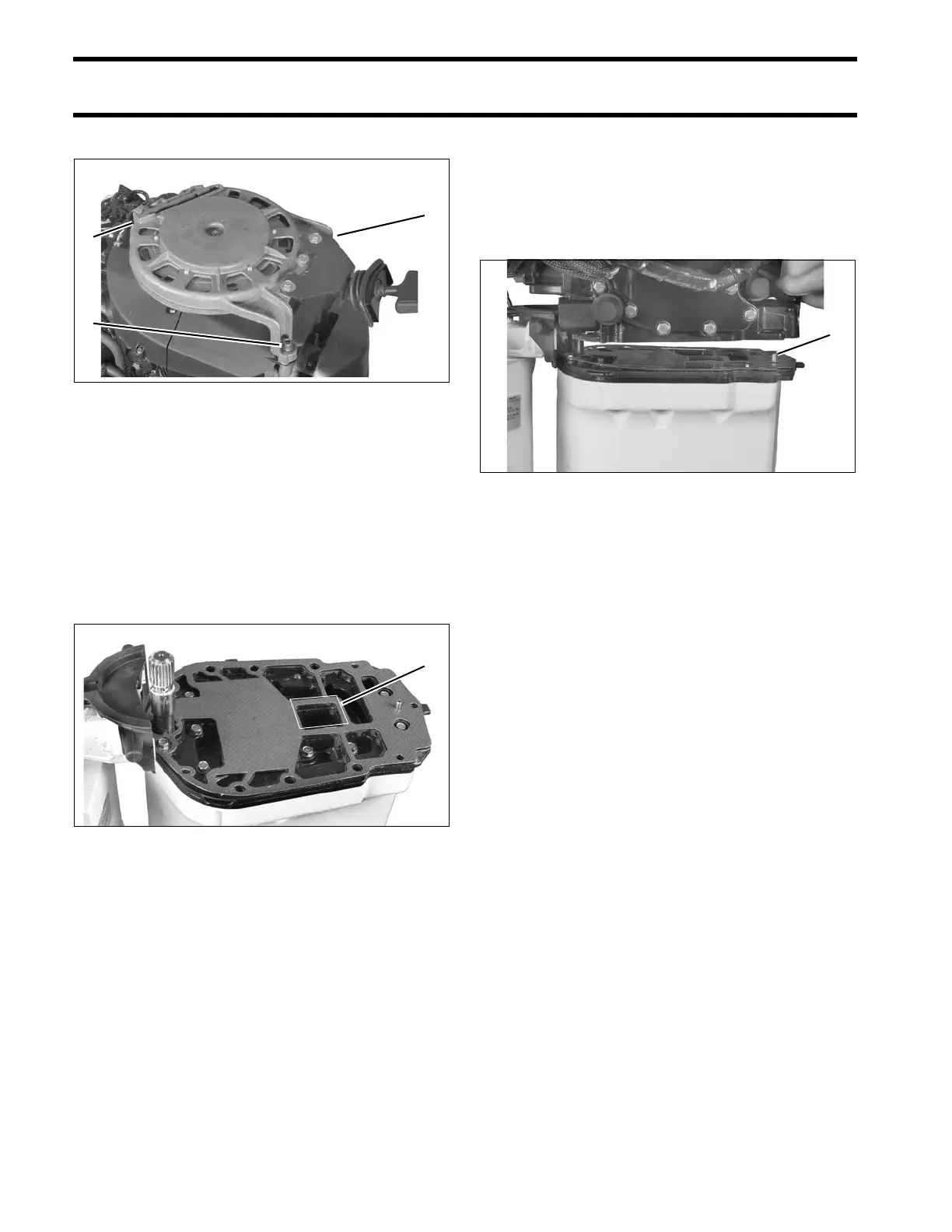
Apply Permatex No. 2 to both sides of a new base
gasket around the exhaust port only. Install gasket
on adapter. To ensure proper sealing, mating sur-
faces must be clean and dry.
Coat the driveshaft splines with Moly Lube. Do not
apply lubricant to end of driveshaft.
Use Lifting Fixture, P/N 396748, and hoist to
slowly lower powerhead onto exhaust housing.
Guide into position over alignment pin at rear of
exhaust housing. If necessary, rotate flywheel in a
clockwise direction to align crankshaft and drive-
shaft splines.
Apply Triple-Guard grease to the threads, and
Gasket Sealing Compound to the shank of the
powerhead screws.
Apply Triple-Guard grease to upper mount screw
threads.
Loosely install all powerhead screws and upper
mount screws before tightening.
• Tighten the six large powerhead screws to a
torque of 18 to 20 ft. lbs. (24 to 27 N·m) in the
sequence shown.
• Tighten the five small powerhead screws to a
torque of 60 to 84 in. lbs. (7 to 9.5 N·m).
1. Starter housing screws (3) 002515
1. Apply Permatex No. 2 here 002164
1. Alignment pin 002162