347
TRIM AND TILT
ELECTRICAL CIRCUIT TESTS
13
Trim Gauge Test
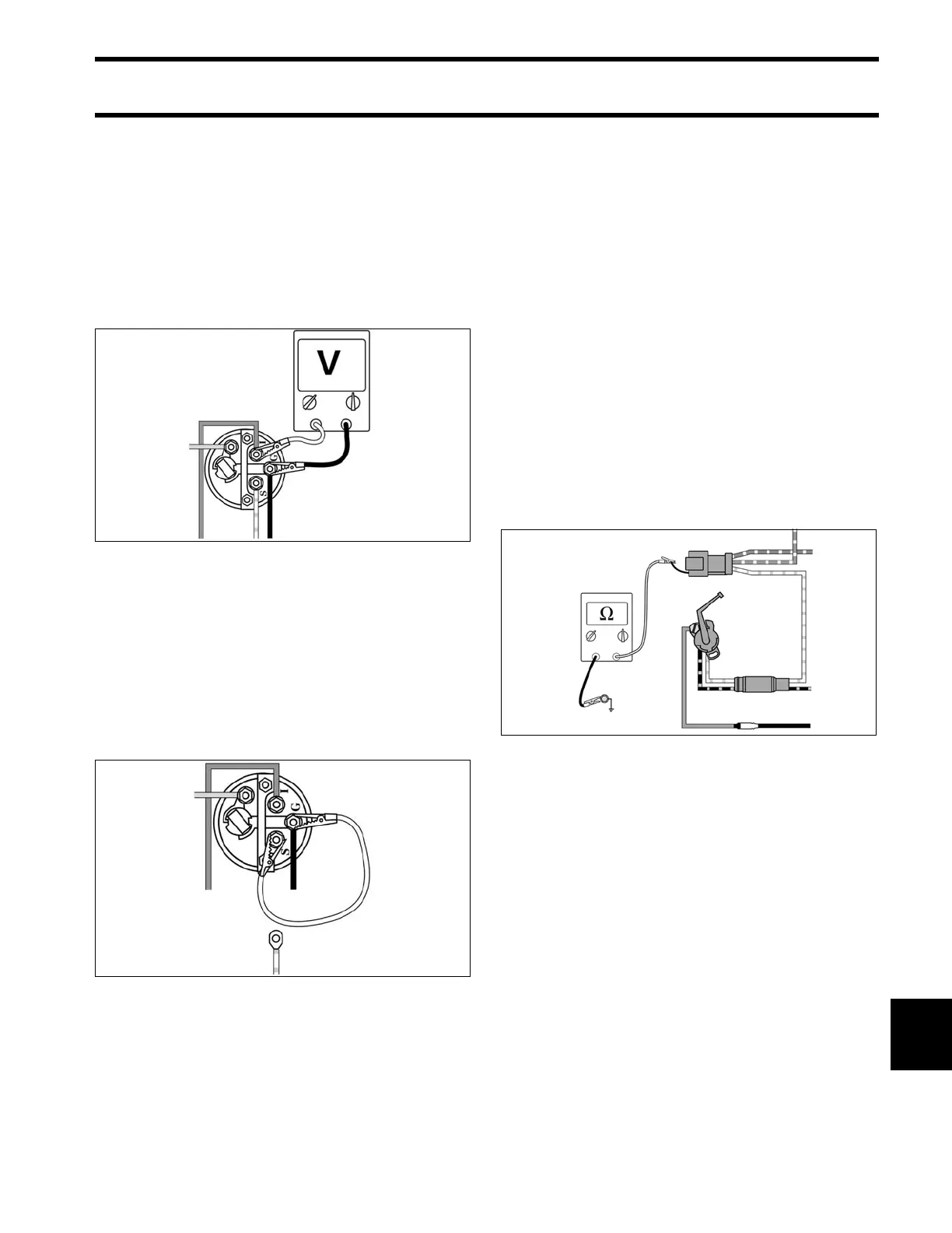
STEP 1
Turn key switch ON. Using a voltmeter, check for
voltage between the trim gauge “I” and “G” termi-
nals.
• If no voltage, check condition of instrument har-
ness, key switch, and engine 20 A fuse.
• If voltage is shown, go to STEP 2.
STEP 2
Remove the white/tan lead from the trim gauge
“S” terminal. With key switch ON, gauge should
indicate full-trim DOWN position. Now connect a
jumper wire between terminals “S” and “G.” Gauge
should indicate full-trim UP position.
• If results are different, replace the trim gauge.
• If results agree, refer to Trim Sender Test.
Trim Sender Test
IMPORTANT: To avoid immediate meter dam-
age, never apply an ohmmeter to an electrical cir-
cuit where voltage is present.
Disconnect the 3-pin connector between the
instrument harness and engine trim harness.
Connect an ohmmeter between the white/tan wire,
terminal “C,” of the engine harness and a clean
engine ground.
With the outboard fully DOWN, meter must show
a reading above 80 ohms.
With the outboard fully UP, meter must show a
reading below 10 ohms.
• If results agree, refer to Trim Gauge Test on
p. 347.
• If results are different, replace trim sender.
DRC6245
DRC6246A
DRC6247