345
TRIM AND TILT
ELECTRICAL CIRCUIT TESTS
13
ELECTRICAL CIRCUIT
TESTS
Relay Testing
When the trim-UP button is pressed, the UP relay
is energized and connects the blue trim motor wire
to the battery positive (+) terminal. The green trim
motor wire remains grounded. When the button is
released, the blue trim motor wire returns to a
grounded position.
When the trim-DOWN button is pressed, the
DOWN relay is energized and connects the green
trim motor wire to the battery positive (+) terminal.
The blue motor wire remains grounded. When the
button is released, the green trim motor wire
returns to a grounded position.
Refer to TILT/TRIM RELAY TEST on p. 110 for
relay testing procedure.
Trim and Tilt Motor
Current Draw Tests
Careful analysis of the electric motor's current
draw and trim/tilt unit operating speed aids evalu-
ation of the electric motor and certain mechanical
components.
Use a battery rated at 360 CCA (50 Ah) or higher
that is in good condition and fully charged to per-
form this test.
IMPORTANT: Specifications are for static
hydraulic tests. DO NOT attempt to perform the
following tests while the boat is moving.
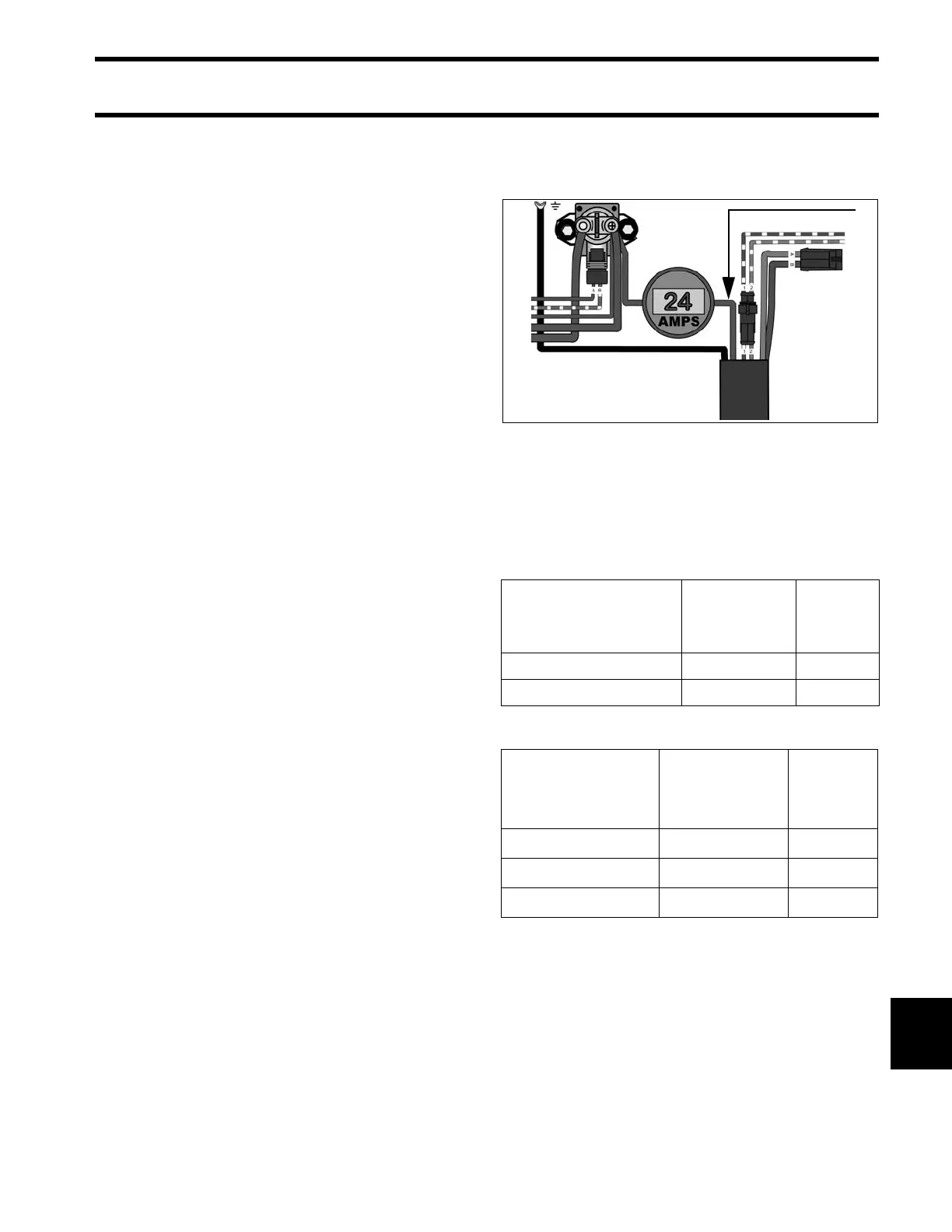
Connect a 0 to 100 A DC ammeter in series
between the battery side of the starter solenoid
and the red lead to the trim/tilt relay module.
Observe ammeter and a stopwatch while running
hydraulic unit through several complete cycles.
Compare test results to the values listed:
75 - 90 HP MODELS
40 - 60 HP MODELS
1. Red lead 005441
Mode
Normal
Current Draw
Time in
Seconds
Full Range UP <30 A 12-18
Full Range DOWN <30 A <18
Stall <40 A –
Mode
Normal
Current Draw
Time in
Seconds
Stall UP 11 to 16 Amps –
Stall DOWN 16 to 22 Amps –
Full Range UP – 13 to 19
Full Range DOWN – 10 to 16