25
ROUTINE SERVICE
OUTBOARD RIGGING CONNECTIONS
2
I-Command Network Connections
If the outboard will be used with I-Command, or
other NMEA 2000 compliant CANbus instruments,
use the following connections to supply informa-
tion to the network:
Remove lower motor covers. Remove air silencer.
Route I-Command Engine Interface Cable around
the front of the throttle body, following the path of
the TPS wiring, and behind the battery cable.
Loosely install tie straps as shown.
To prevent wire chafing, harness
must be routed below the flywheel cover.
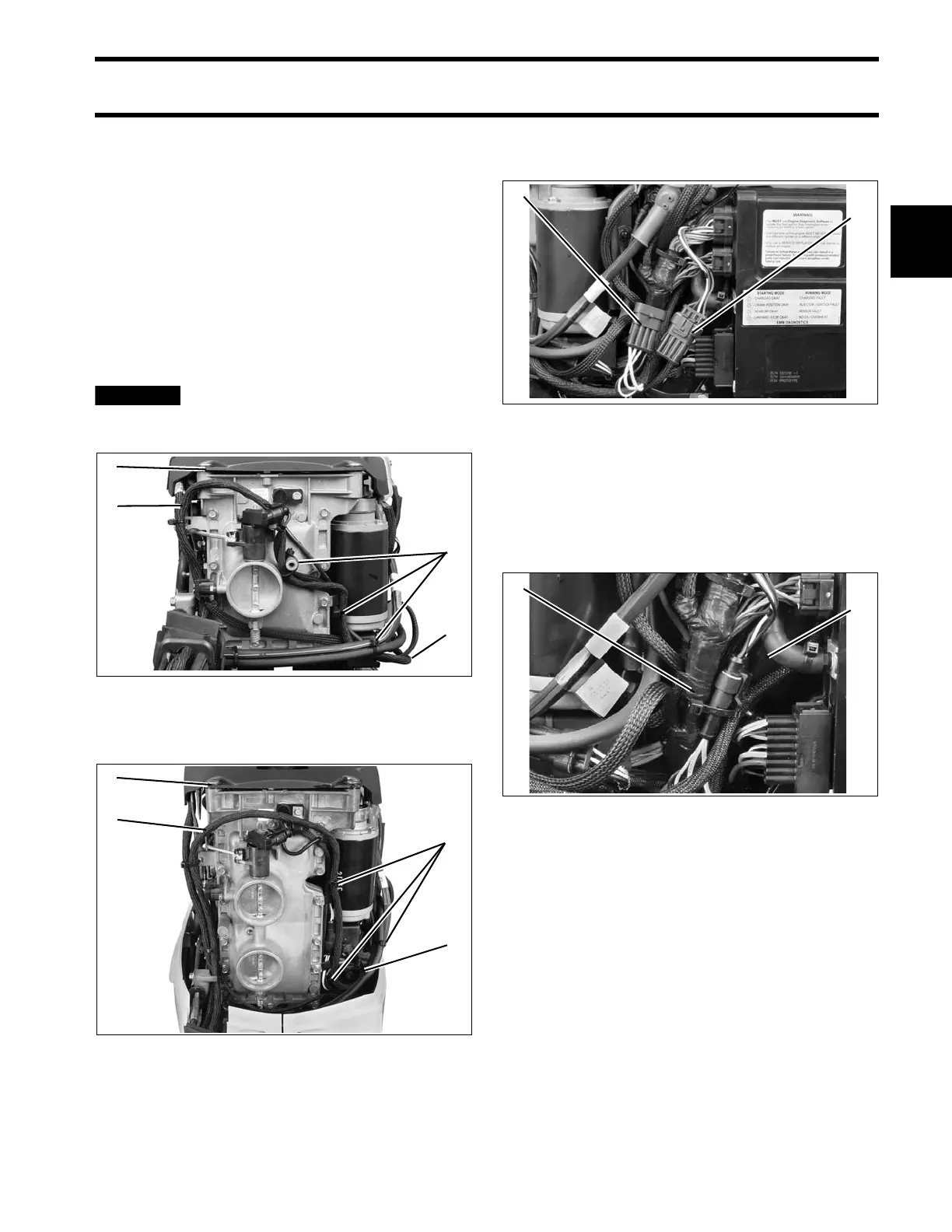
Connect the I-Command Engine Interface Cable
to the EMM CANbus connector.
2 CYLINDER MODELS
To prevent interference with engine cover latch,
bundle excess wiring behind EMM cooling water
hose. Secure I-Command connectors to back side
of engine harness with tie strap.
2 Cylinder Models
1. Flywheel cover
2. Harness routing
3. Tie straps
006736
3 Cylinder Models
1. Flywheel cover
2. Harness routing
3. Tie straps
006742
1. I-Command network connector
2. EMM CANbus connector
006735
1. Engine harness
2. EMM cooling water hose
006738