186
COOLING SYSTEM
TEMPERATURE SENDER SERVICING
TEMPERATURE SENDER
SERVICING
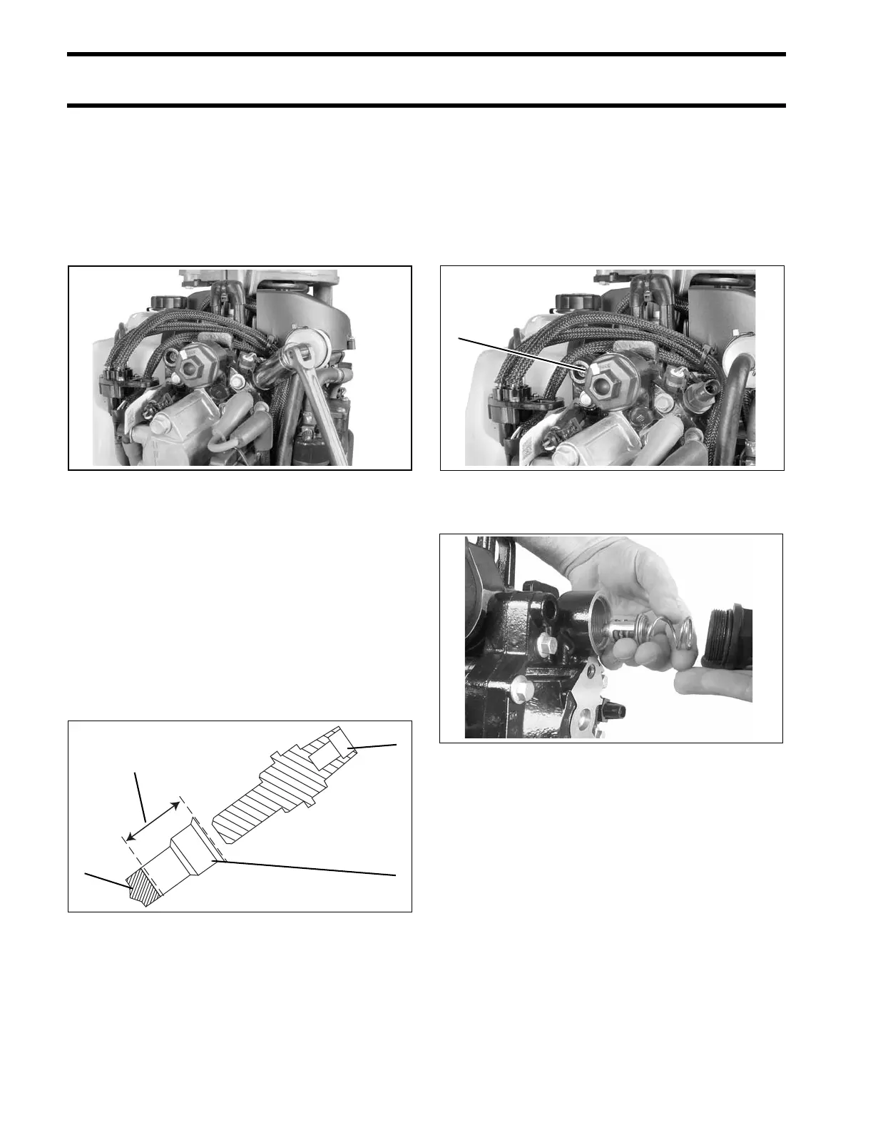
Removal
Loosen sensor and remove by hand. Use care to
avoid breaking threads.
Clean sensor threads, sensor, and sensor cavity.
Installation
Fill bottom of sensor cavity with 0.7 cc of Thermal
Joint Compound, P/N 322170. Sensor cavity
should be filled to 1 inch (25 mm) below the top
edge of the cavity.
Install sensor. DO NOT use gasket sealing com-
pound. SLOWLY tighten temperature sensor to a
torque of 50 to 70 in. lbs. (5.6 to 8.0 N·m).
Wait 10 minutes for trapped air to bleed from cav-
ity. Thermal compound may seep past threads.
Retighten sensor.
THERMOSTAT
SERVICING
Disassembly
Remove the thermostat cover and O-ring from cyl-
inder head.
Remove spring, thermostat, and gasket.
Remove the cylinder head if cylinder head ther-
mostat seal requires replacement. Place new seal
in the cylinder head with side marked “TO CYL
HEAD” facing thermostat. Refer to Cylinder Head
008346
1. Temperature sensor
2. Sensor cavity
3. Thermal joint compound
007049
008347
002444