360
TRIM AND TILT
TRIM AND TILT SERVICE
Trim Motor
Refer to Removal on p. 348 for trim and tilt
assembly removal procedure.
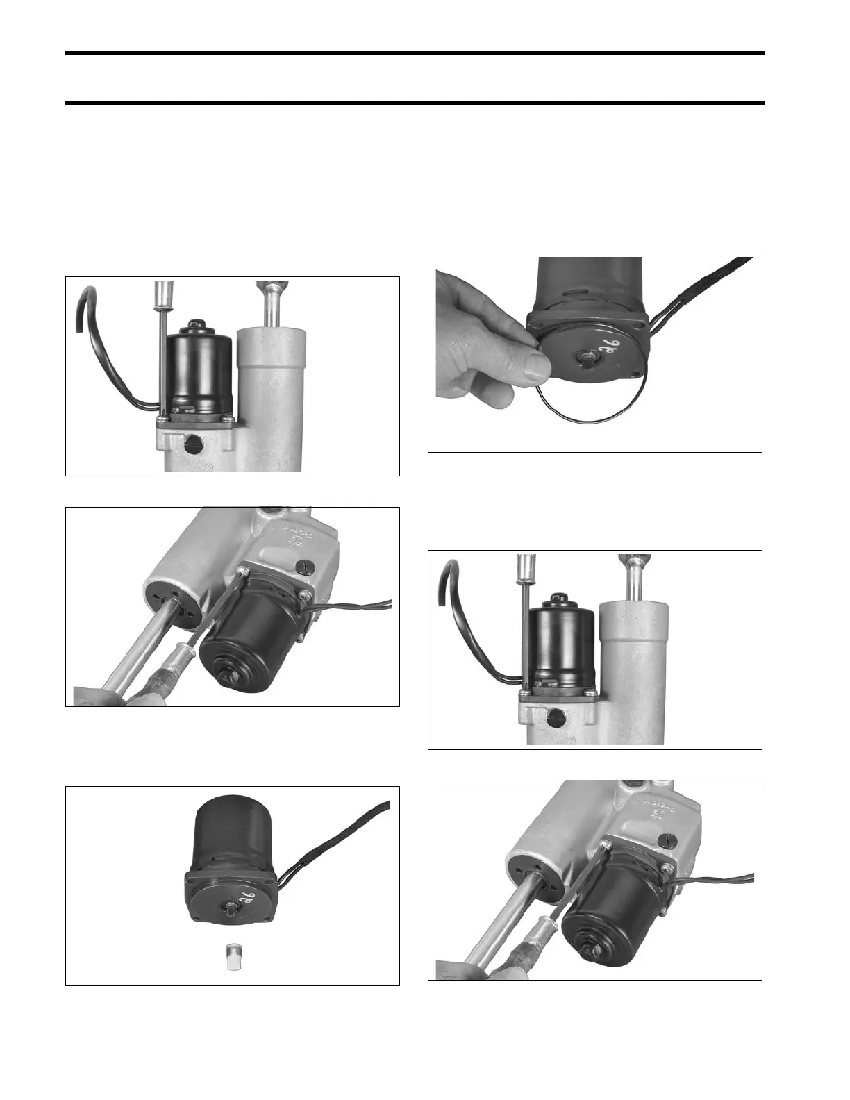
Removal
Remove the four large motor flange retaining
screws. Remove the motor and discard O-ring,
screws, and washers.
Remove drive coupler from either the motor or the
pump assembly.
Installation
IMPORTANT: Use only Evinrude/Johnson Bio-
degradable TNT Fluid to fill the hydraulic system.
Install drive coupler in pump assembly.
Install a new motor O-ring.
Position the motor on the manifold and install four
new screws and lock washers. Tighten the screws
35 to 50 in. lbs. (4 to 5.6 N·m).
40 - 60 HP Models 002531
75 - 90 HP Models 004282
002532
002533
40 - 60 HP Models 002531
75 - 90 HP Models 004282