79
SYSTEM ANALYSIS
DIAGNOSTIC PROCEDURES
5
Troubleshooting
Outboard will not crank, starter does not
operate:
• Check condition of battery and cables (main
battery switch and cables). Make sure battery
cables are not reversed.
• Confirm that switched B+ is present at “A” termi-
nal (yellow/red wire) of starter solenoid with key
switch in the START position.
• Check ground at “B” terminal harness connec-
tion.
• Refer to ELECTRIC START TESTS on p. 106.
Repair starter or start circuit as needed.
Outboard cranks, will not start:
• Check emergency stop switch and lanyard
• Check powerhead mounted neutral switch
• Check the EMM LED Indicators for system sta-
tus information. Refer to EMM LED INDICA-
TORS on p. 81.
• Use the Evinrude Diagnostics software
Occurred Faults screen to check for current ser-
vice codes. If there are multiple occurred sensor
codes, inspect all 5 V sensor circuits for broken
or grounded wiring.
• Perform a Static Ignition test using Evinrude
Diagnostics software and an inductive timing
light. Refer to Static Ignition Test on p. 85.
• If ignition test indicates steady spark, refer to
FUEL DELIVERY TESTS on p. 88.
Outboard runs, low on power, misfires:
•
Check the EMM LED Indicators for system sta-
tus information. Refer to EMM LED INDICA-
TORS on p. 81.
• Use the Evinrude Diagnostics software Monitor
screen to check system (55 V) and TPS volt-
ages. System voltage should be steady, and
TPS voltage should be between 0.2 and 4.85 V.
IMPORTANT: Use a digital multimeter to check
voltage on external circuits only when necessary.
All EMM output currents are DC current.
• Use the diagnostics software Dynamic Tests to
isolate a faulty cylinder. See DYNAMIC TESTS
on p. 80.
• Use an inductive timing light to check ignition
and fuel injector circuits. Refer to Running Igni-
tion Tests on p. 86 and Running Fuel System
Tests on p. 89.
• Use the diagnostics software Fuel Control
Adjustment test to help identify a cylinder that
may be too rich or too lean. Refer to Fuel Con-
trol Adjustment on p. 80.
• Use an inductive amp meter to monitor injector
circuit current. Compare readings of all circuits
to identify possible failure.
• Check fuel quality and that fuel is present at
injectors.
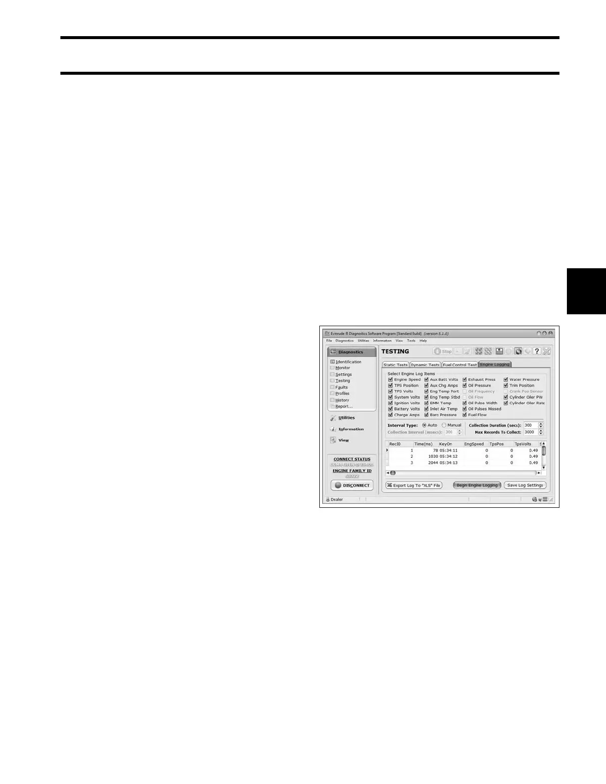
• Use the diagnostics software Logging function
to record engine data as a problem is occurring.
• AFTER all the above inspections, if the cause of
a running quality problem still cannot be identi-
fied, perform a compression test to check for
internal powerhead damage.
IMPORTANT: Remove a cylinder head or disas-
semble the engine only as a last resort.
Logging Screen 008574