58
ENGINE MANAGEMENT MODULE (EMM)
DESCRIPTION
DESCRIPTION
The Engine Management Module (EMM) is a
water-cooled engine controller. It controls many
outboard systems including alternator output for
the 12 V and 55 V circuits. Operating voltage is
supplied to the EMM by the stator.
This section discusses the functions of the EMM
and its various internal and external sensors. It
also describes using Evinrude Diagnostics soft-
ware to retrieve and adjust service information
saved in the EMM
EMM Functions
The EMM controls the following processes and
functions:
• Alternator output; 55 V and 12 V
• Fuel and ignition timing and duration
• Fuel injector activation
• Oil injector pump activation
• Electric fuel pump control
• Idle speed control
• RPM limiter
• Electrical circuit monitoring
• Service code creation and storage
• Warning system activation
• ROM verification, self-test
• Choke-less cold starting
• Output of diagnostic data
• Tachometer signal
• RPM profile and engine hours
• Oiling ratios
• Exhaust water valve activation (60 - 65 HP)
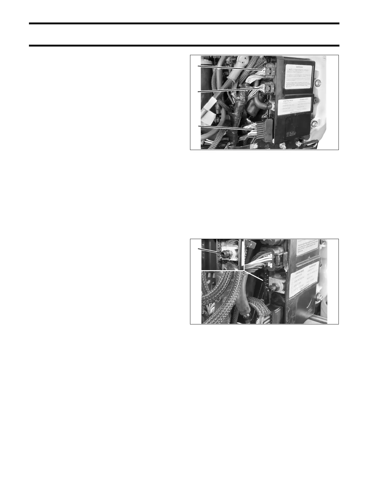
EMM Connections
IMPORTANT: EMM connections and wiring
must be clean and tight. Improper electrical con-
nections can damage the EMM. DO NOT run the
outboard with loose or disconnected wiring.
Make sure EMM connections are clean and tight.
• Engine wire harness to EMM connectors; J1-A,
J1-B, J2
• Stator to EMM connections; one 6-pin AMP and
J2 connector.
LED Indicators
The EMM has four LED indicators located next to
the electrical connectors that provide useful infor-
mation about the status of the system.
IMPORTANT: LED 1 is toward the top of the
outboard (Closest to EMM J1-B connector).
When the ignition key is turned ON, LEDs 3 and 4
should light, indicating that sensor circuits and the
stop circuit are working.
As the outboard is being started, all four LEDs
should light and then go off in sequence. If any of
the LEDs does NOT light during starting, refer to
EMM LED INDICATORS on p. 81.
When the outboard is running, all LEDs should be
off. If any LED is lighted while the outboard is run-
ning, refer to EMM LED INDICATORS on p. 81.
1. J1-A connector
2. J1-B connector
3. J2 connector
006487
1. LED indicators
(Cooling hose removed for clarity)
002429
006467