296
GEARCASE SERVICE, 40 – 60 HP MODELS
SHIFT ROD ADJUSTMENT
slide water pump down over key. Be sure impeller
key does not fall out of position.
Make sure the impeller engages the
impeller key. Serious powerhead damage will
result if impeller key is not in place.
Align the impeller housing with the gearcase.
Apply Gasket Sealing Compound to threads of the
four impeller housing screws. Install the screws
and tighten to a torque of 60 to 84 in. lbs. (7 to 9.5
N·m).
Install the water tube grommet on the impeller
housing.
Apply a thin bead of Adhesive 847 to groove of
the impeller housing grommet. Install the grommet
on the impeller housing.
Before installing gearcase, shift rod
adjustment MUST be checked. Refer to SHIFT
ROD ADJUSTMENT on p. 296.
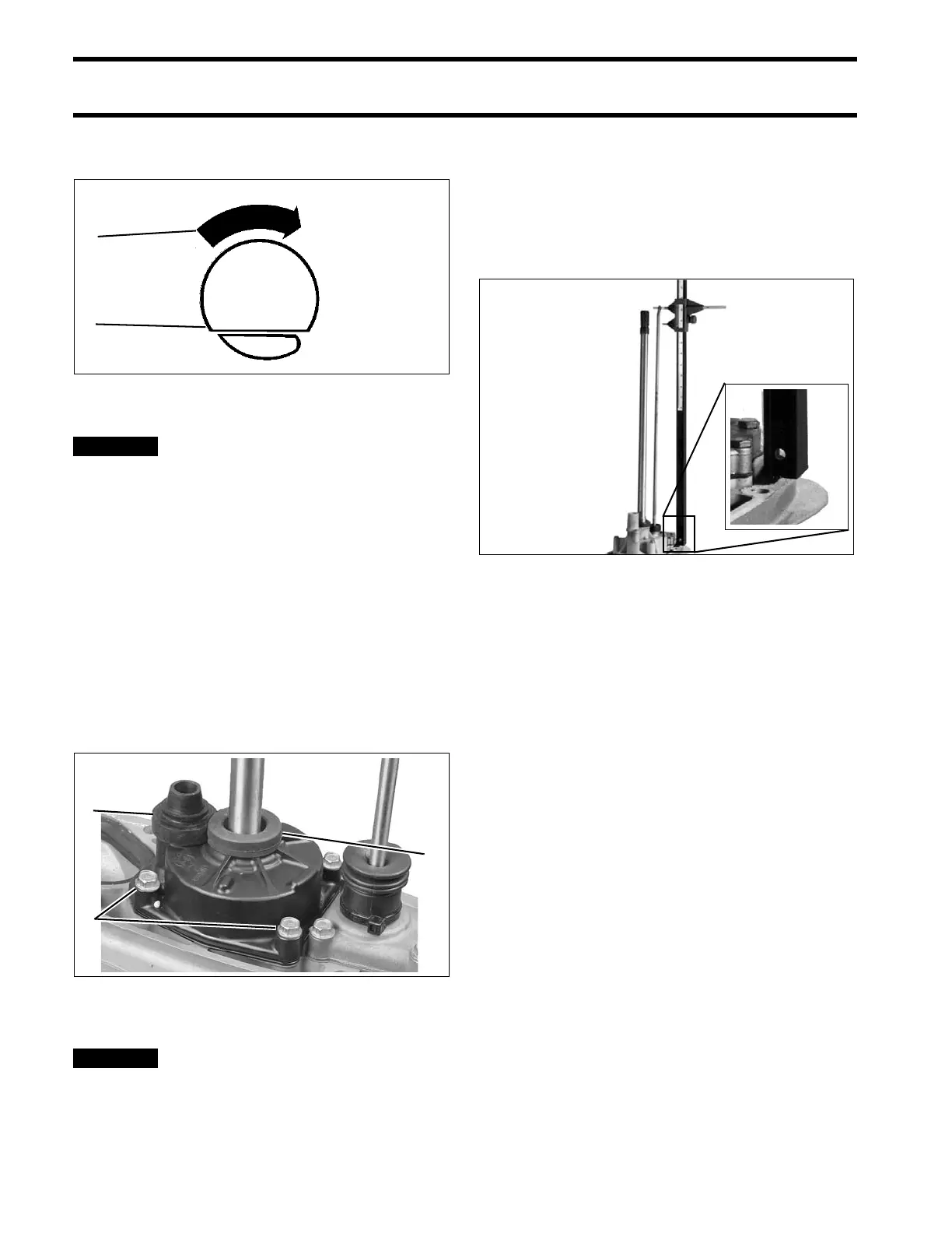
SHIFT ROD
ADJUSTMENT
Check the shift rod height from the shift rod hole to
the surface of the gearcase using Universal Shift
Rod Height Gauge, P/N 389997.
With the gearcase in NEUTRAL, rotate the shift
rod up or down as necessary for correct adjust-
ment. Once correct height is achieved, rotate rod
one half turn or less to direct offset to the rear.
Shift Rod Height:
• 21.38 in. (543 mm) ± One-Half Turn
1. Sharp edge of drive key
2. Direction of driveshaft rotation
CO2995
1. Housing screws
2. Water tube grommet
3. Impeller housing grommet
001203
COA6166