104
ELECTRICAL AND IGNITION
ELECTRIC START CIRCUIT
ELECTRIC START CIRCUIT
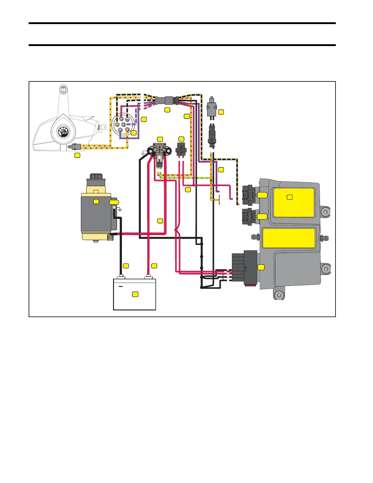
Start Circuit Diagram
1
2
3
5
6
7
8
12
13
14
15
16
9
10
11
7
6
5
4
3
2
1
8
9
18
17
16
15
14
13
12
11
10
13
12
11
10
17
16
15
14
34
33
32
31
30
29
28
27
26
24
25
23
22
21
20
19
18
FUSE
J1-B
J1-A
J2
4
B
A
–
NEG
A
B
2
1
6
5
4
15
10
+
23
M
A
S
C
M
B
1
2
3
4
5
6
2
1
7
8
9
9
11
12
13
14
1
1. Marine battery 9. PURPLE wire (switched B+)
2. RED wire (POS) 10. Engine Management Module (EMM)
3. BLACK wire (NEG) 11. YELLOW/RED wire, start
4. Starter solenoid 12. Neutral Safety Switch (remote control)
5. Fuse (10 amp) 13. Neutral Safety Switch (engine)
6. RED/PURPLE wire 14. RED starter motor cable
7. Key switch connectors 15. Electric starter motor
8. Ignition switch