103
ELECTRICAL AND IGNITION
CHARGING SYSTEM TESTS
6
Following the manufacturer’s directions, connect
the variable load tester (carbon pile) across the
battery terminals. Stevens model LB-85 and
Snap-On model MT540D are examples of testers
available.
Start and run the outboard at approximately 5000
RPM. Use the variable load tester to draw the bat-
tery down at a rate equivalent to the stator’s full
output.
• The ammeter should indicate nearly full output,
approximately 25 A @ 5000 RPM.
Decrease the battery load toward 0 A.
• Ammeter should show a reduced output. As the
current draw decreases, the battery voltage
should stabilize at approximately 14.5 V.
• If results vary, check stator BEFORE replacing
the EMM. Refer to STATOR TESTS on p. 101.
55 V Alternator Circuit
Check battery ground cable for continuity.
With the key switch ON, check battery voltage at
battery (12 V).
Then, use Electrical Test Probe Kit, P/N 342677,
and a digital multimeter set to read 55 VDC to
check voltage on white/red wires at J2 connector
of EMM. Voltage at EMM connector should be 0.5
to 1 V less than battery.
With outboard running at 1000 RPM, voltage on
white/red wires should be 55 V. Voltage readings
at a specific speed (RPM) should be steady.
If there is any other reading, refer to STATOR
TESTS on p. 101. Inspect the stator wiring and
connections. Inspect the capacitor wiring, connec-
tions, and capacitor. Repair the wiring or replace a
faulty capacitor, stator, or EMM.
A WARNING
Excessive battery discharge rates might
overheat battery causing electrolyte gas-
sing. This might create an explosive atmo-
sphere. Always work in a well ventilated
area.
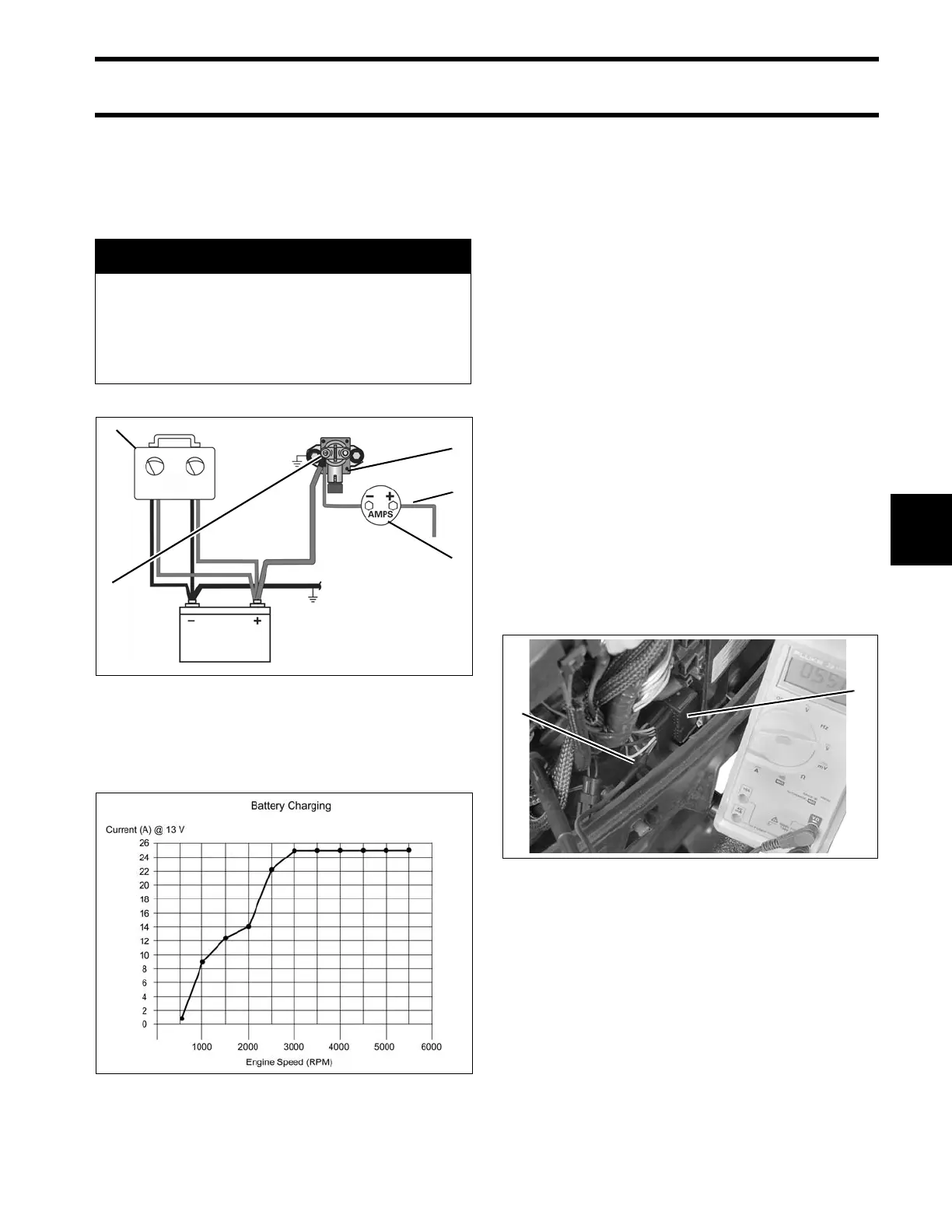
Variable Load Test Diagram
1. Red wire (alternator output from EMM)
2. Starter solenoid
3. Battery cable terminal (B+)
4. Variable load tester
5. Ammeter
002077
Battery Charging Graph 002076
1. J2 connector
2. Test probe
007261