174
OILING SYSTEM
OIL COMPONENT SERVICING
2-CYLINDER MODELS
ALL MODELS
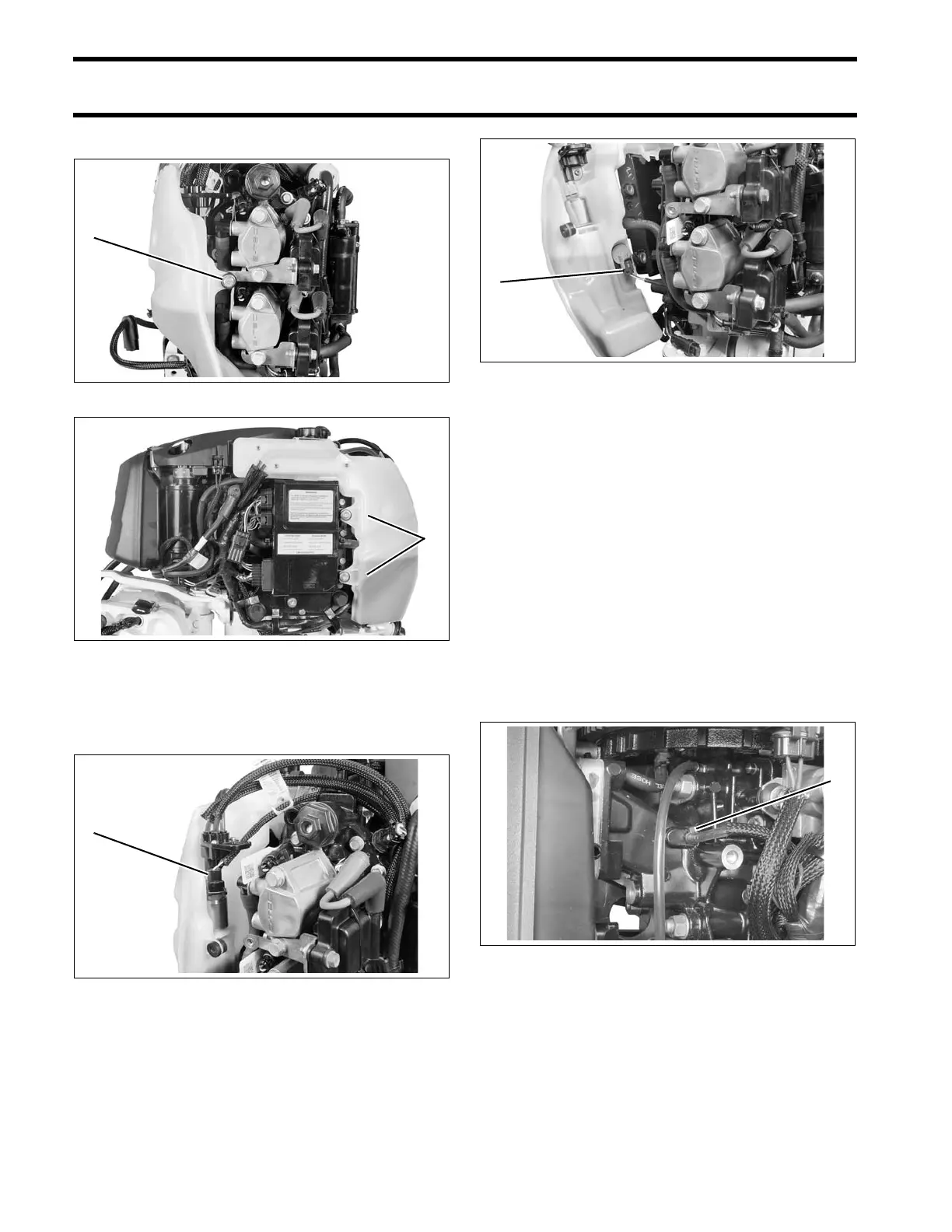
Disconnect the electrical connector to the oil injec-
tion pump and manifold assembly.
Disconnect the electrical connector to the low oil
switch.
IMPORTANT: Note oil distribution hose rout-
ings before proceeding with disassembly.
Remove oil distribution hoses from the manifold.
Installation
Position oil tank assembly on powerhead. Clean
mounting screws and apply Nut Lock to threads.
Install screws and tighten to a torque of 30 to 42
in. lbs. (3.5 to 5 N·m).
Install protective sleeves and route oil distribution
hoses from the oil distribution manifold to the
crankcase oil delivery fittings. Refer to OIL SUP-
PLY DIAGRAMS on p. 160. Secure oil hoses to
crankcase fittings with tie straps.
Run outboard and check for leaks. Use Evinrude
Diagnostics software to activate “Oil Prime.”
Check oil flow through oil distribution hoses.
Check oil system operation and routing of oil sys-
tem hoses.
Repair any oil leaks and kinked or misrouted
hoses. Install air silencer and engine covers.
1. Screw 008073
1. Screws 008074
1. Oil pump connector 008075
1. Low oil switch connector 008076
1. Tie strap 006573