134 (167) BRUKER Installation Manual Version 001
Sample Heater Option
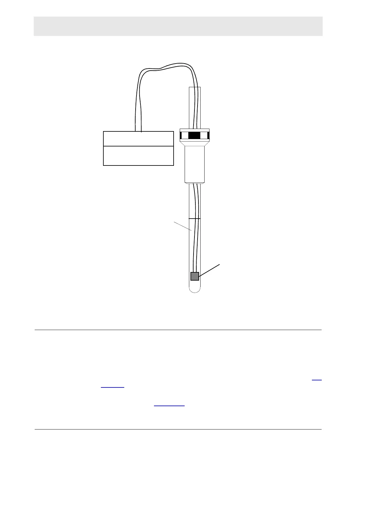
Figure 13.3. TEST MEASURE
B-ACS Heater Power Supply 13.2
The B-ACS HEATER POWER SUPPLY (Part No. H1455) is used in connection
with the B-ACS SAMPLE HEATER 120C (Part No. H1385).
The Unit, up to series No.34, contains two PK100 (Part/No.14514) modules from
VERO, each 22-26V / 5A, so the Power Supply will run at a maximum of 10A fig-
ure 13.4.
The Unit at series No. 35 contains one PK240 (Part/No.16524) module from
VERO 22-26V/10A figure 13.5
.
Adjusting the PK100 parallel 13.2.1
Take out one of the two power Modules (PK100) and perform the following steps
with the remaining one.
PT100
Thermistor
100.000
°C
OIL
 Loading...