152 (167) BRUKER Installation Manual Version 001
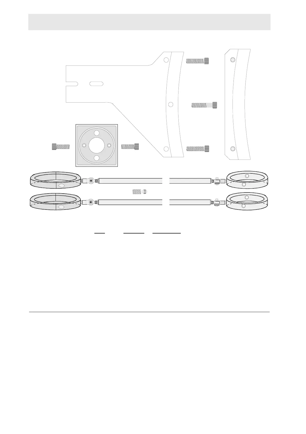
Figure B.2. Parts Required for Assembly on 500 MHz Magnet
Mounting the Base Plate B.2.2
Remove the holding screw from the front of the magnet as shown in figure B.3.
Place the base plate under the rim of the magnet and fasten it to the magnet, us-
ing the 4.7 cm machine screw (refer to figure B.4). Do not tighten the screw com-
pletely, allow some movement for adjustments.
Place the upper support bracket on top of the base plate as shown in figure B.4.
Secure it using the two 4.3 cm machine screws. Tighten these two screws and the
screw holding the base plate securely.
Mount the column support bracket with the bottom side down (as shown in figure
B.4), using the two 3.3 cm machine screws. Tighten the screws hand tight, allow-
ing some free play for later adjustments.
Top ViewSide View
Plastic Screws (6 pieces)
A
Part Requirements:
Item Quantity Description
A 1 Base Plate
B 1 Upper Support Bracket
C 1 Column Support Bracket
D 2 Machine Screws 3.3 cm
E 2 Machine Screws 4.3 cm
F 1 Machine Screw 4.7 cm
G 2 Adjustable Arm Assembly
H6 Plastic Screw
B
C
D
D
E
E
F
(Viewed from Above)
G
G
H
 Loading...