20 (167) BRUKER Installation Manual Version 001
Mounting Instructions
(see Figure 4.1.). Tip: It is easier to accomplish this step with two people, one to
hold the column vertical and the other to secure the adjustable arms.
Note: If the magnet has Vibration Dampers and the column uses a support pic-
tured in Figure 4.1.
, then the column must be leveled at this time (as described in
section 4.9
) before mounting the pneumatic arm assembly.
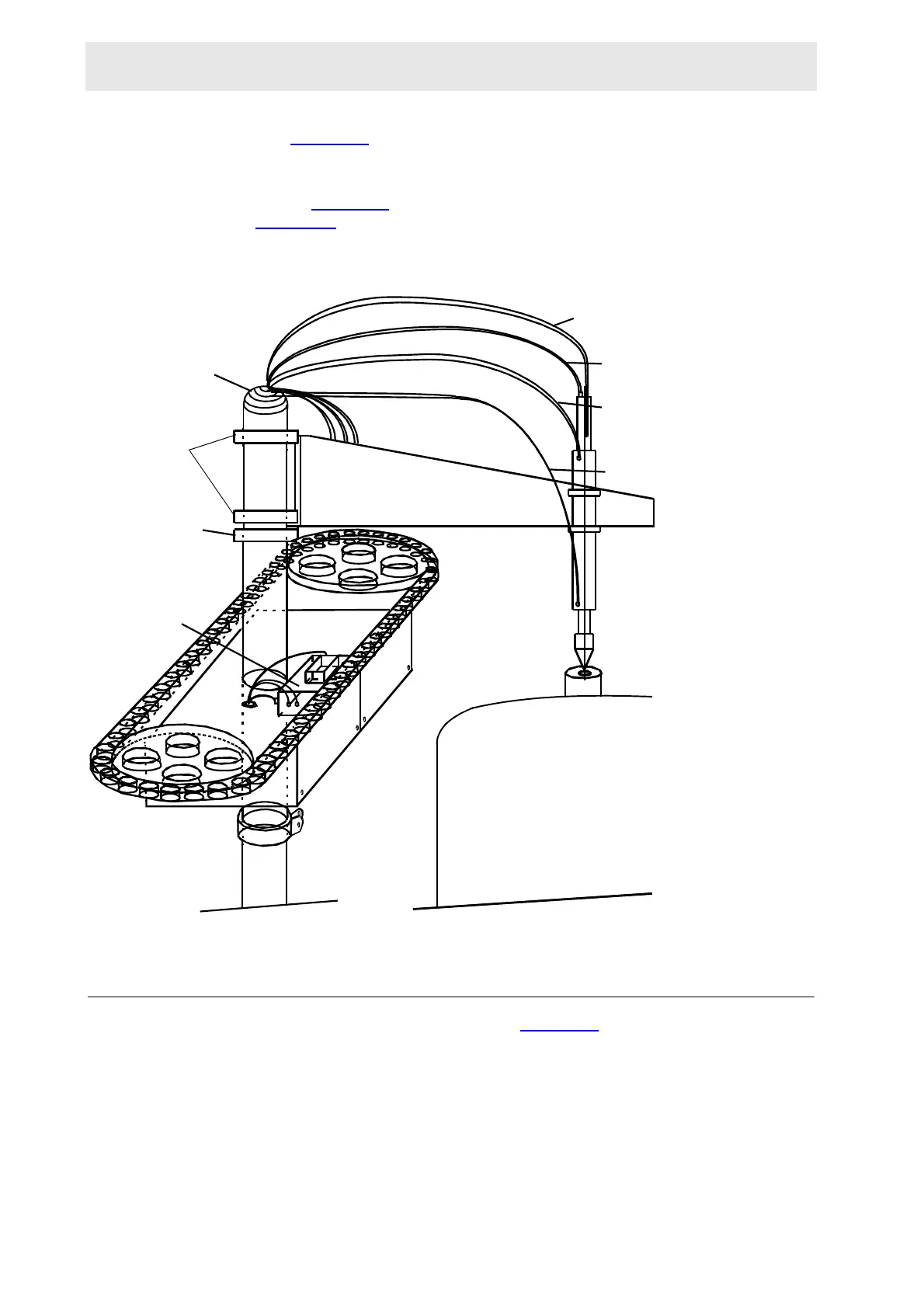
Figure 4.8. Arrangement of Arm and Cabinet Assemblies
Mounting the Pneumatic Arm Assembly 4.8
Slide the pneumatic arm resting ring (Figure 4.8.) over the top of the round col-
umn piece and let it rest on the top of the cabinet (don’t tighten it). The resting ring
gives a vertical support to the arm which can still rotate horizontally. A key and slot
system allows for a free rotation of the arm of about 90° around the column. This
is necessary on wide bore magnets where the arm has to swing away from the top
opening when handling larger samples.
LIGHT
BARRIER (at the)
Magazine
PNEUMATIC
ARM
RESTING
RING
PNEUMATIC ARM ASSEMBLY
UPWARD MOTION
AIR HOSE
DOWNWARD MOTION
AIR HOSE
PINCHER AIR HOSE
VERTICAL MOTION & PINCHER
SWITCH CONNECTIONS
FLEXIBLE
RUBBER
SLEEVE
MAGNET
FIXTURE
RINGS
 Loading...