Installation Manual Version 001 BRUKER 149 (167)
Final Adjustments A.2.4
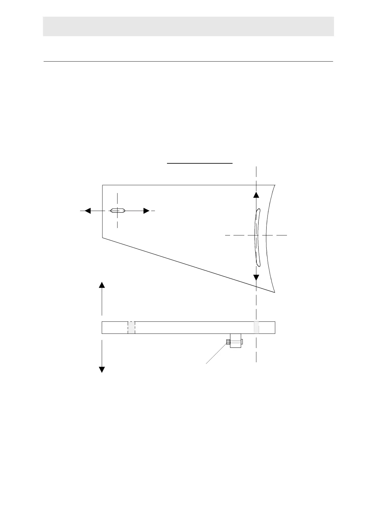
Move the column assembly until it is approximately horizontally and vertically lev-
el. Tighten the adjustable arm assembly (both ends). Move the column and base
plate to the left or right until the right side of the square column (as you face the
magnet) is 38mm to the left of the center of the magnet (as shown in figure A.1).
Recheck the horizontal and vertical level using a water level. Adjust the adjustable
arm assemblies and/or the adjustment screws on the base plate (figure A.1 and
A.4) until the column is horizontally and vertically level.
Figure A.4. Adjustment Possibilities on the Base Plate
Check the column once again to see if the right side of the column is still 38mm
from the center of the magnet. Adjust if necessary.
Recheck the horizontal and vertical level and the distance, making adjustments
until both are correct.
Tighten all of the remaining screws.
ADJUSTMENT
Adjustment Screw
 Loading...