Installation Manual Version 001 BRUKER 155 (167)
Figure B.6. Base Plate and Adjustable Arm Assembly
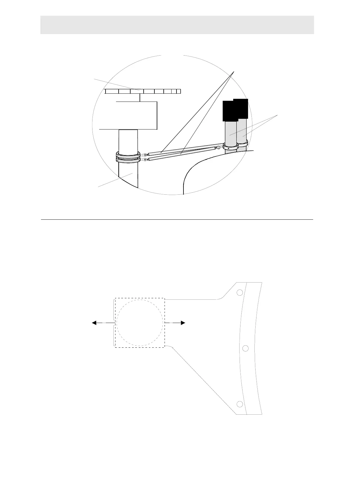
Final Adjustments B.2.4
Move the column assembly until it is approximately horizontally and vertically level
by intermittently turning the adjustable arm assembly rods and the column support
bracket forwards or backwards (figure B.8). Tighten the adjustable arm assembly
(both ends) and the two screws holding the column support bracket.
Figure B.7. Adjustment Possibilities for the Column Assembly
CABINET
MAGAZINE BELT
MAGNET
ADJUSTABLE ARM
ASSEMBLY
COLUMN
N2 TOWER
 Loading...