84 (167) BRUKER Installation Manual Version 001
Circuit Diagrams
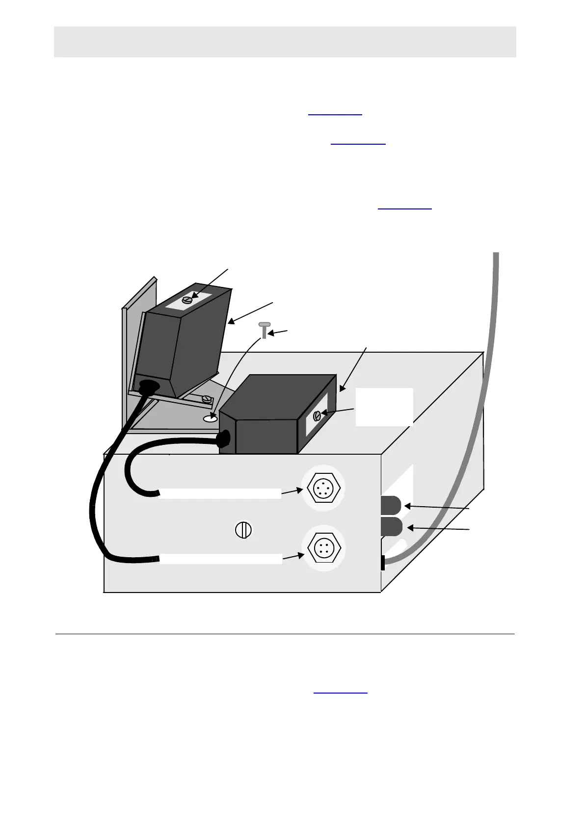
On the back of the light barrier cabinet there are two plug connections, the top
one is for the B-ACS 60 light barrier optic cable and the bottom one is for the B-
ACS 120 light barrier optic cable (figure 11.17
).
When you are using a B-ACS 120 you must install a second light barrier optic at a
right angle to the first as illustrated in figure 11.17
. The B-ACS 120 optic is se-
cured with a screw on top of the light barrier cabinet. Plug the cable from the B-
ACS 120 light barrier optic into the bottom plug connector at the back of the light
barrier case.
Three optic sensors within the optics, indicate whether the inside (M60) or outside
(M120) position of the magazine belt is occupied (figure 11.18
).
Figure 11.20.Rear Side of the Light Barrier Cabinet
Adjusting the Light Barrier Cabinet and Optics 11.3.4
Position Switch
The position of a sample on the magazine belt is adjusted with the position switch
located at the bottom of the Optic (figure 11.18
). This adjustment will ensure that
the pneumatic arm reaches the exact position repeatedly when the magazine belt
moves forwards or backwards.
Screw
M120 Light Barrier Optic
M60 Light Barrier Optic
LED 1
LED 2
M120 Cable Connection
M60 Cable Connection
Distance
Adjustment
Screw
Distance Adjustment Screw
 Loading...