154 (167) BRUKER Installation Manual Version 001
Mounting the Column Assembly B.2.3
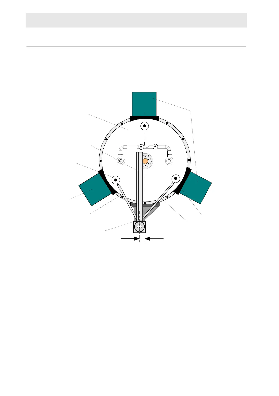
Place the column assembly with the attached cabinet onto the column support
bracket so that the square column piece is perpendicular to the center of the mag-
net (see figure B.5).
Figure B.5. Top View of the 500 MHz Magnet with Sample Changer
Place the magnet end (the smaller ring) of the adjustable arm assemblies over the
N2 towers as shown in figures B.5, B.6 and B.8. Align the arms so they are as hor-
izontally level as possible, ensuring that the arms do not touch the magnet.
38 mm
COLUMN
ADJUSTABLE ARM
ASSEMBLY
COLUMN LEGS
N2 TOWER
N2 TOWER
ADJUSTABLE ARM
ASSEMBLY
COLUMN LEGS
PNEUMATIC ARM
MAGNET
 Loading...