26 (167) BRUKER Installation Manual Version 001
Mounting Instructions
inet end of the 230V power cable to the Mains Connection as shown in Figure
4.10..
Connect cable # 5 to LISH 5 on the Cable and Pneumatic Hose Connection Panel
(Figure 4.5.
and Figure 4.13.). Connect the other end of the cable to the Light
Barrier for the Shim System as shown in Figure 4.3.
. For magnets with the BOSS
1 and BOSS 2 Shim Systems (see Figure 4.2.
) the cable is connected directly to
the BSMS SLCB board, Sample Control connector.
Connect the RS232 connector and cable from the computer to the Remote Con-
trol 9-pin female connection on the Cable and Pneumatic Hose Connection Panel
(Figure 4.13.
).
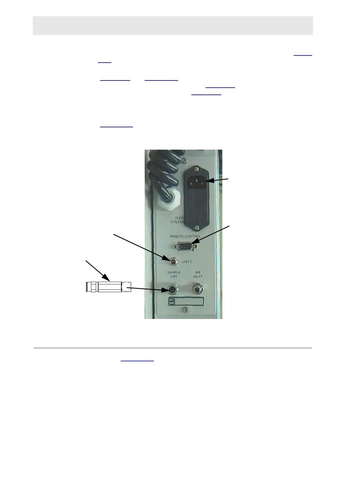
Figure 4.13. Cable and Pneumatic Hose Connection Panel
Description of Input and Output Locations 4.11
Refer to Figure 4.13..
Input: Mains connection - The 230V Connector
Air Input - Air Inlet
Light Barrier Shim System Input
Output: Sample lift air output - Sample Lift. Parallel with buffer.
Input and Output: RS232 Cable connection to computer - Remote Control
230V POWER
CONNECTOR
FOR RS232
CABLE
ONE-WAY
VALVE
For BSMS
 Loading...