146 (167) BRUKER Installation Manual Version 001
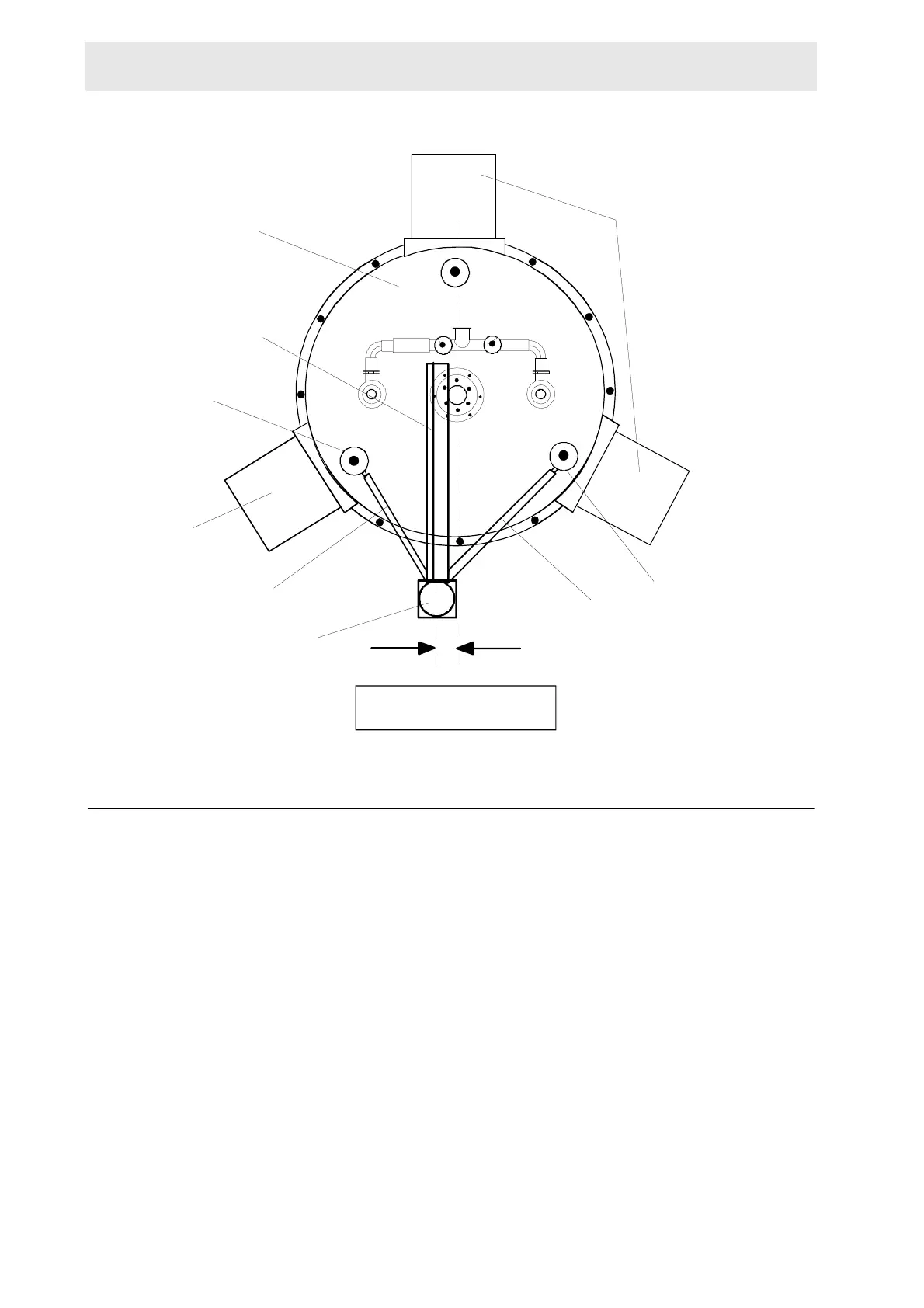
Figure A.1. Top View of the Magnex Magnet with Sample Changer
Mounting the Column Assembly A.2.3
Place the column assembly with the attached cabinet on to the stand column plate
of the base plate in such a manner that the square column piece is perpendicular
to the center of the magnet (see figure A.1).
Place the magnet end of the adjustable arm assemblies over the N2 towers as
shown in figures A.3 and A.4. Align the arms so they are as horizontally level as
possible, ensuring that the arms do not touch the magnet. Refer to figures A.2 and
A.4.
PLAN VIEW
KST 25.09.96 MAGNEX04.DS4
38 mm
COLUMN
ADJUSTABLE ARM
ASSEMBLY
COLUMN LEGS
N2 TOWER
N2 TOWER
ADJUSTABLE ARM
ASSEMBLY
COLUMN LEGS
PNEUMATIC ARM
MAGNET
 Loading...