14 (167) BRUKER Installation Manual Version 001
Mounting Instructions
Preparing the Magnet for Installation 4.2
The bottom arms of the sample changer are designed to fit 65 mm φ legs, they are
adjustable in length to allow for compensation of construction tolerance.
If for some reason it is not possible to move, fix, or align the legs of the magnet,
new bottom arms at the proper length can be delivered as an option. Please in-
form a Bruker representative about the misalignment angle or the necessary arm
length, new arms will be shipped as soon as possible.
Connecting the Light Barrier Assembly 4.3
➪ Note: Magnets with the BOSS 1 and BOSS 2 Shim Systems do not require
this step, they are delivered with the light barrier cylinder already installed.
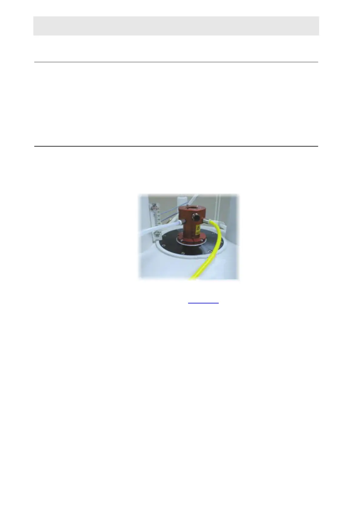
Figure 4.2. Magnet with BOSS Shim System Already Mounted
Mount the light barrier cylinder by placing it onto the top of the shim system and
fastening the three side screws (Figure 4.3.
). To correctly place the light cylinder
barrier, push the cylinder down firmly while turning the cylinder into position (the
fitting may be tight). This will guarantee minimal loss of sample lift air between the
shim system and the cylinder.
 Loading...