Securing the Bottom of the Column Assembly
Installation Manual Version 001 BRUKER 21 (167)
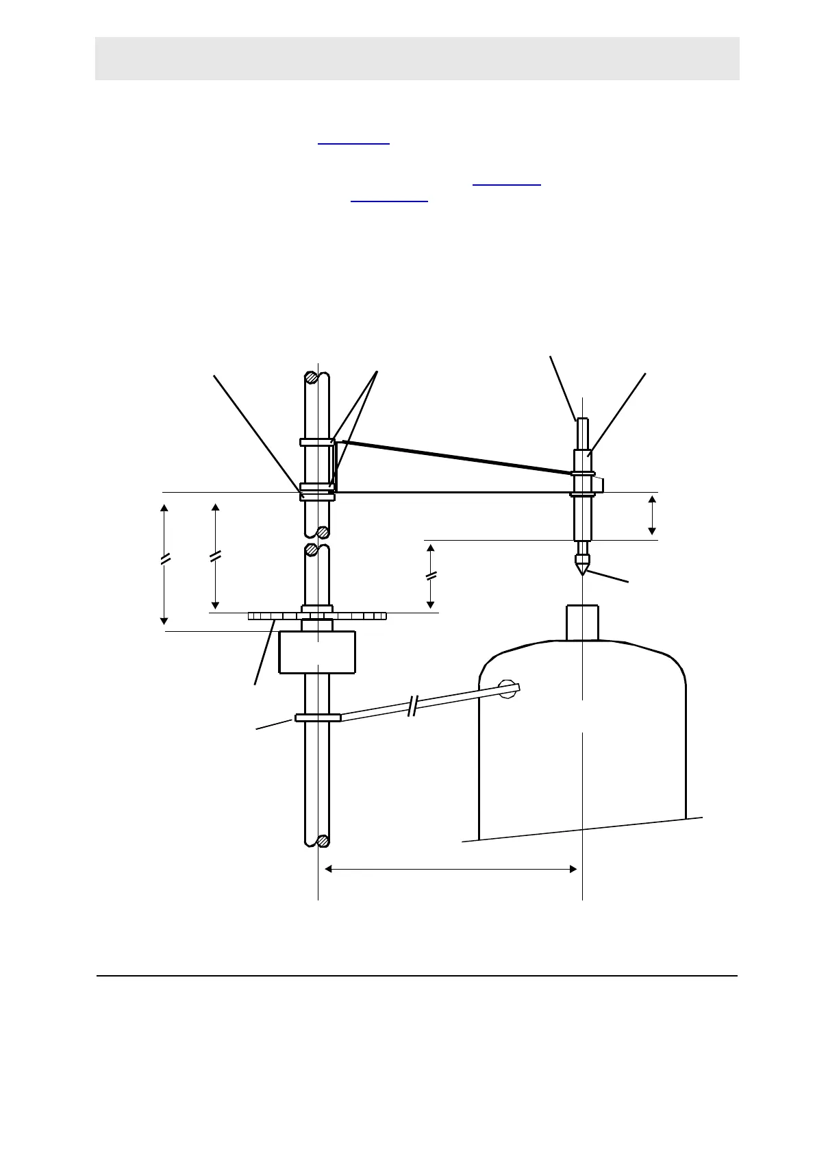
Place the pneumatic arm assembly over the top of the column, sliding the two fix-
ture rings (Figure 4.8.
) over the round column piece. Tighten the rings just
enough to keep the pneumatic arm assembly from sliding down.
Rotate the pneumatic arm assembly (Figure 4.8.
) until the pincher is directly over
the shim system Figure 4.10.
). The distance between the bottom of the pincher
(when the cylinder is in the down position) and the top of the shim system should
be 3 cm. Adjust this distance by loosening the fixture rings and raising or lowering
the pneumatic arm assembly. When the correct distance is achieved, tighten the
fixture rings. Raise the pneumatic arm resting ring until it rests firmly against the
bottom fixture ring and tighten it securely.
Figure 4.9. Position of the Pneumatic Arm on the Column
Securing the Bottom of the Column Assembly 4.9
Using a level measuring device, check to see if the round column piece is vertical-
ly level. Move the bottom of the column assembly as needed to adjust the level.
PINCHER
VERTICAL
CYLINDER
FIXTURE
RINGS
PISTON
PNEUMATIC ARM
RESTING RING
MAGAZINE BELT
TOP FASTENING
RING
CABINET
MAGNET
558
90
277
440
APPROX
395
APPROX
PNEUMATIC ARM
 Loading...