24 (167) BRUKER Installation Manual Version 001
Mounting Instructions
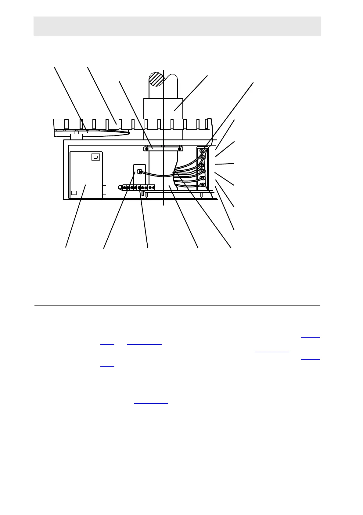
Figure 4.11. Partial Front View of Column and Cabinet
Remote Hose Connections 4.10.1
The pressure of the compressed air supply should be between 4 and 6 bar (50-60
PSI). Connect the one-way valve supplied in the accessory kit to the sample lift
valve on the Cable and Pneumatic Hose Connection Panel as shown in Figure
4.12.and Figure 4.13.. Add the needle valve supplied in the accessory kit be-
tween the sample lift valve and the BSMS as shown in Figure 4.12.
. Assemble
the pneumatic piping on and around the sample changer as shown in Figure
4.13..
Open the compressed air supply.
Using the regulator at the rear of the lower column assembly, set the air pressure
to 4 bar (50 PSI). Plug the Sample Changer pneumatic connections to the console
as shown in Figure 4.13.
.
WHEEL
BELT
CABINET
RESTING
RING
CYLINDRICAL
COLLAR
SENSOR
CONNECTOR
ASSEMBLY
VERTICAL
SENSORS
HORIZONTAL
SENSORS
HORIZONTAL
POSITION
MAGAZINE
POSITION
LIGHT BARRIER (at the)
SHIM SYSTEM
LIGHT BARRIER
(at the) MAGAZINE
1
2
3
4
5
6
SIDE
OPENING
COLUMN
PUSH BOTTONS
FOR MANUAL
MOTION
AND TESTING
CONNECTOR
LIFT VALVE
POWER
SUPPLY
 Loading...