36 (167) BRUKER Installation Manual Version 001
Settings and Adjustments
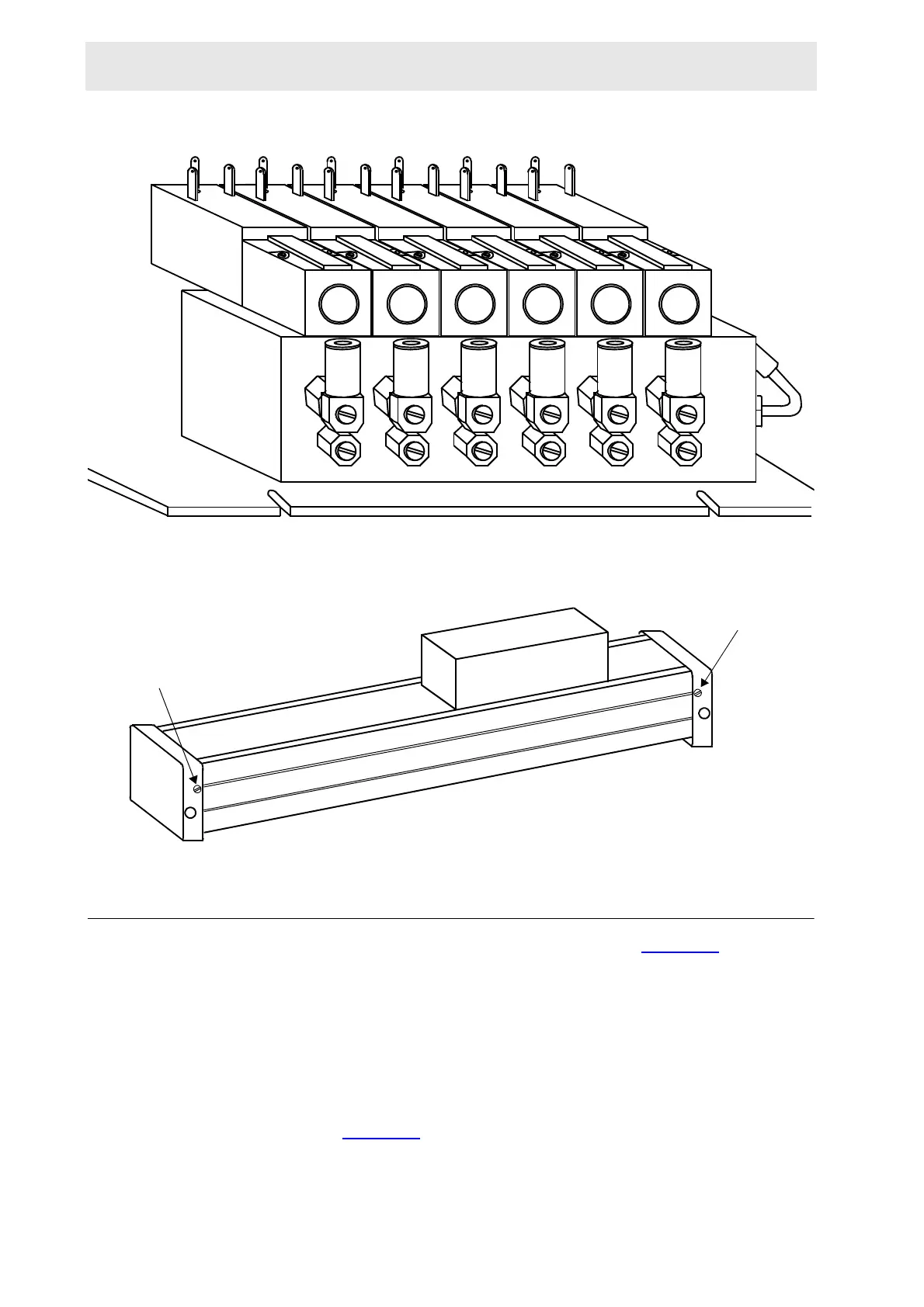
Figure 5.7. Outlet Needle Valves on the Cylinder Supply Connections
Figure 5.8. ORIGA Horizontal Cylinder Pneumatic Setting
Final Setup 5.5
Switch off the power by pushing the red security switch (Figure 5.2.).
Push all boards in firmly.
Check the following connections:
9 lead flat cable to the RS232.
16 lead flat cable to the Interface Board.
9 lead flat cable from the Front Panel to the Interface Board.
Switch the power on by pulling the red security switch out and pushing the black
start button (Figure 5.2.
).
The initialization routine will automatically begin.
0
1
2
3
4
5
END OF COURSE
NEEDLE VALVE
END OF COURSE
NEEDLE VALVE
 Loading...