B-ACS Interface Board Diagram
Installation Manual Version 001 BRUKER 85 (167)
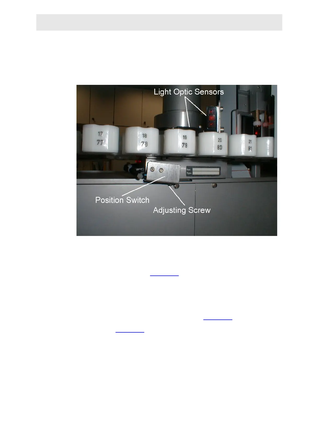
To make the adjustment turn the screw at the bottom of the switch until the pinch-
er on the pneumatic arm is in the middle of the sample position on the magazine
belt.
Figure 11.21.Location of the Position Switch on the Light Barrier Cabinet
Adjusting the M60 Light Barrier Optic
The adjustment of the reflex key for the detection of a sample at the inside posi-
tion of the magazine belt is made through a distance adjustment screw on the
side of the sensor optic (figure 11.17
). The range of the optics view should be be-
tween the middle and the outside of the magazine belt position.
You must ensure that the M60 optic detects a sample only in the inside magazine
belt position, not the outside position, and likewise that the M120 optic detects a
sample only in the outside position, not the inside.
The Light Barrier Magazine Board is located on the rear side of the rear panel of
the light barrier cabinet. The M60 Optic cable (figure 11.19
) is connected to this
board through the upper connector on the rear panel of the light barrier cabinet as
shown in figure 11.17
.
 Loading...