3-18 2002 Buell P3: Engine
HOME
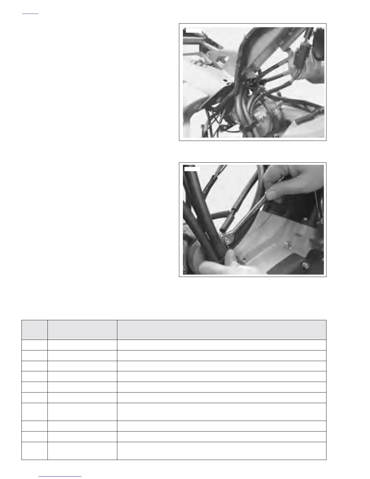
12. See Figure 3-30. Tighten hose clamps using Hose
Clamp Pliers, part no. HD-41137.
13. See Figure 3-31. Tighten nut on hose routing clamp.
14. Install rear shock. See 2.15 REAR SHOCK ABSORBER.
15. See Table 3-4. Electrical Items for Engine Assembly
Connect the following electrical items:
Figure 3-30. Tighten Hose Clamps
Figure 3-31. Tighten Clamp
7635
7718
Table 3-4. Electrical Items for Engine Assembly
Item
no.
Description Location
1Ignition module [10] Located on frame backbone.
2Speedo sensor [65] Located under seat (right side-tucked in under cavity).
3Side stand switch [60] Tie wrapped to rear brake line.
4Neutral switch [131] Disconnect at neutral switch.
5Oil pressure switch [120] Disconnect at oil pressure switch.
6Alternator stator [46] Located under seat (left side).
7Starter solenoid wire
[128]
Disconnect at starter.
8Spark plug wire Located on spark plug.
9Battery—positive wire Disconnect at main circuit breaker.
10 Rear brake light switch
[121]
Located under frame by shock absorber.