2002 Buell P3: Engine 3-19
HOME
16. Install clutch cable at hand lever location. See 6.4
CLUTCH.
17. Install drive belt. See 1.11 DRIVE BELT AND REAR
SPROCKET.
18. Install front sprocket cover. See 2.22 SPROCKET
COVER.
19. Install master cylinder onto footpeg bracket. See 2.21
FOOTPEGS AND FOOTPEG SUPPORT BRACKETS.
a. Apply several drops of LOCTITE
®
THREAD-
LOCKER 243 (blue) to last few threads.
b. Tighten to 4-6 ft-lbs (5-8 Nm).
NOTE:
SEE TOP END ASSEMBLY SECTION. The steps mentioned
previously complete Assembly preparation for top end servic-
ing. You may now proceed with TOP END ASSEMBLY PRO-
CEDURES. Then proceed to step 22.
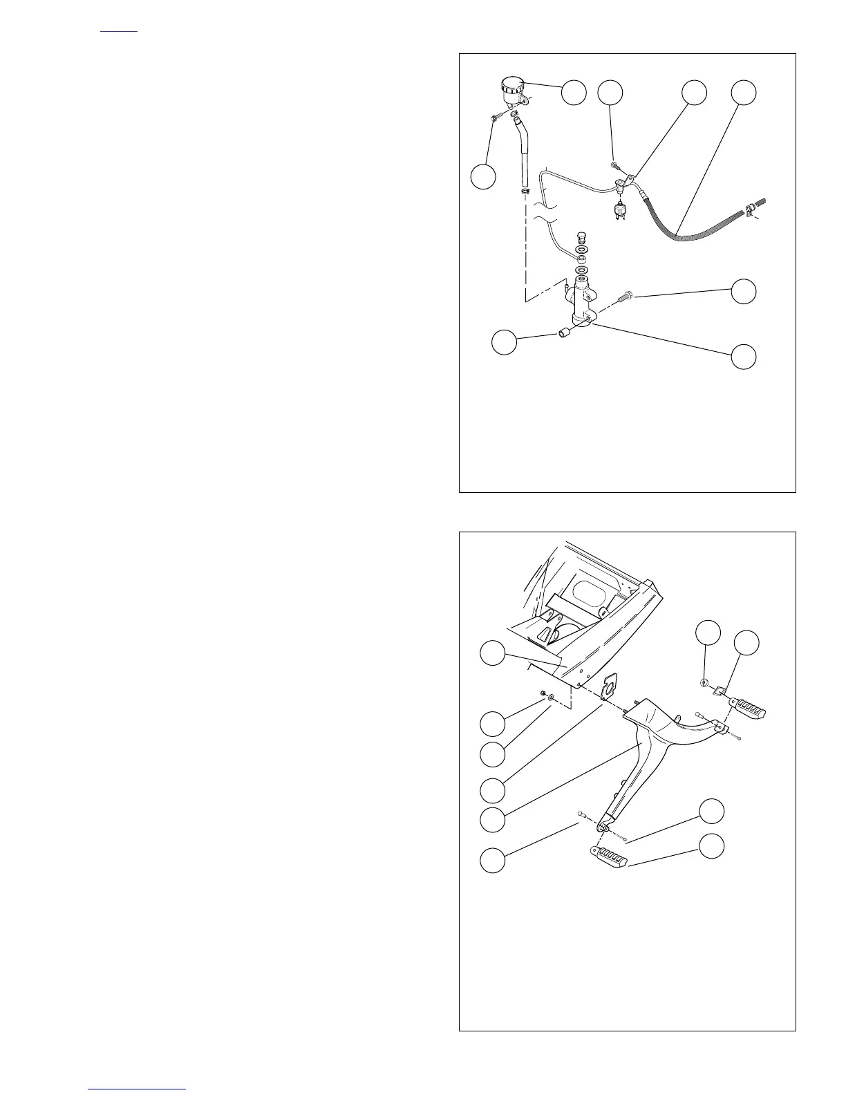
Figure 3-32. Brake Line Assembly
Figure 3-33. Footpeg Bracket Assembly
1. Screw
2. Brake Fluid Reservoir
3. Screw
4. Brake Line Bracket
5. Screw
6. Brake Line
7. Master Cylinder
8. Spacer
1
3
6
7
8
2 54
a0017x3x
1. Frame
2. Locknut
3. Washer
4. Spacer
5. Footrest Support Bracket
6. Clevis Pin
7. Footpeg
8. Cotter Pin
9. Index Plate
10. Spacer
a0016x3x
1
2
3
4
5
6
8
7
10
9