3-58 2002 Buell P3: Engine
HOME
Bushing Inspection and Removal
1. See Figure 3-98. Bushings are press fit in gearcase
cover and crankcase. Inspect each bushing against its
corresponding cam gear shaft or pinion gear shaft. See
Tabl e 3-13.
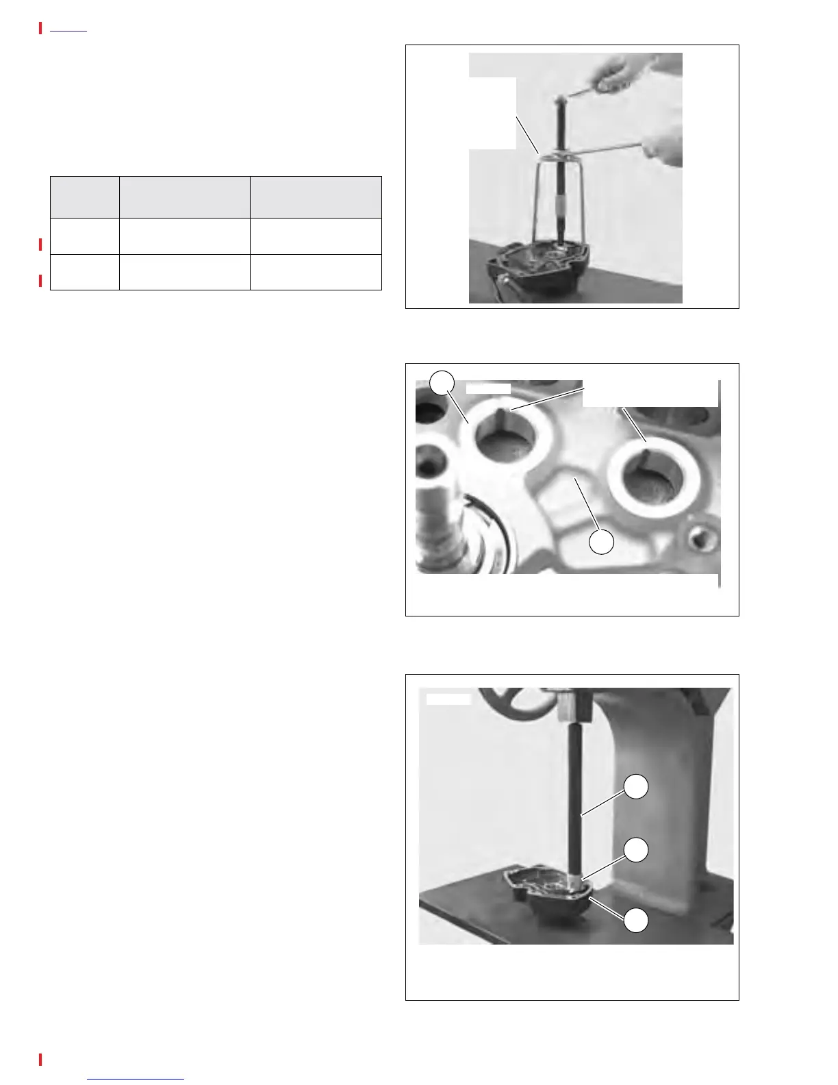
2. See Figure 3-102. Use a BUSHING AND BEARING
PULLER (Part No. HD-95760-69A) to remove bushings
from gearcase cover and crankcase.
Bushing Installation
NOTE
Installing and reaming crankcase and gearcase cover bush-
ings may alter the center distances between mating gears
and may result in an increase in gear noise. For quiet-running
gears, the gears should be matched to the center distances.
CAM GEAR BUSHINGS IN RIGHT
CRANKCASE HALF
1. See Figure 3-103. Each cam gear bushing, to be
installed in right crankcase half, must be positioned in
crankcase bore with its oiling slot at crankcase slot.
2. Using an arbor press, UNIVERSAL DRIVER HANDLE
(Part No. HD-33416), and CAMSHAFT NEEDLE BEAR-
ING (Part No. HD-97273-60) install each bushing in its
crankcase bore so that bushing shoulder contacts crank-
case boss.
3. See Bushing Reaming. After you install a new bushing
in right crankcase half, ream the bushing to correct size.
CAM GEAR BUSHINGS (EXCEPT INTAKE
BUSHING) IN GEARCASE COVER
1. See Figure 3-104. Using an arbor press, install each
bushing in its gearcase cover bore so that bushing shoul-
der contacts cover boss. Position each bushing so the
oiling slot is at the 3 o’clock position within the gearcase
cover bore.
2. See Bushing Reaming. After you install a new bushing
in gearcase cover, line-ream the bushing to correct size.
Table 3-13. Gear Shaft Specifications
GEAR
SHAFT
CORRECT
CLEARANCE
SERVICE WEAR
LIMIT
Cam 0.0007-0.0022 in.
(0.0178-0.0559 mm)
0.003 in.
(0.076 mm)
Pinion 0.0023-0.0043 in.
(0.0584-0.1092 mm)
0.0050 in.
(0.1270 mm)
Figure 3-102. Removing Bushing
Figure 3-103. Cam Gear Bushing Installed in Crankcase
Figure 3-104. Arbor Press
Bushing and
Bearing Puller
(Part No. HD-
95760-69A)
7674806a
1. Cam Gear Bushing
2. Right Crankcase Half
Oiling slot must be at
12 o’clock position
7678
1
2
1. Gearcase
2. Camshaft Bushing Installer (Part No. HD-97273-6
3. Universal Driver Handle (Part No. HD-33416)
7706
1
2
3