3-66 2002 Buell P3: Engine
HOME
involved could cause parts to “fly out” with considerable
force. Inadequate safety precautions could result in
death or serious injury.
9. See Figure 3-116. Mount the left crankcase half and fly-
wheel assembly on a press table, supporting crankcase
on parallel bars. Press on end of sprocket shaft with
arbor press until flywheel assembly is free from crank-
case half. Do not drive flywheel assembly from crank-
case half as flywheels may be knocked out of alignment.
NOTE
See Figure 3-117. If it is necessary to remove either the pin-
ion shaft bearing or sprocket shaft bearing, proceed as fol-
lows:
10. Gearshaft bearing will remain on flywheel pinion shaft.
Remove retaining ring, and bearing may be slipped off
pinion shaft.
11. See Figure 3-118. Place flywheel assembly in FLY-
WHEEL SUPPORT FIXTURE (Part No. HD-44385). Pull
sprocket shaft bearing with SPROCKET SHAFT INNER
Figure 3-116. Pressing Flywheel from Crankcase
Press on end of
sprocket shaft
7689
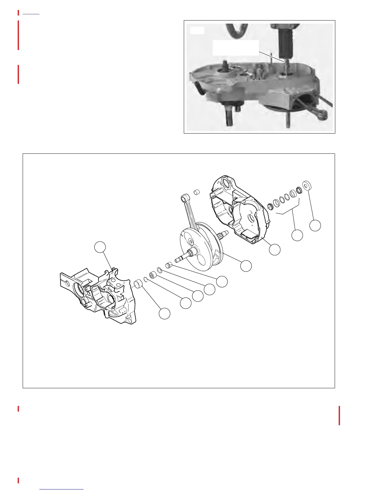
Figure 3-117. Crankcase and Flywheel Assembly
1. Oil Seal
2. Bearing Assembly
3. Crankcase Half
4. Connecting Rod and Flywheel Assembly
5. Inner Race
6. Retaining Ring
12. Gear Shaft Bearing
13. Retaining Ring
14. Outer Bearing Race
15. Crankshaft Half
a0084x3x
1
2
3
4
5
6
7
8
9
10