7-8 2002 Buell P3: Electrical
HOME
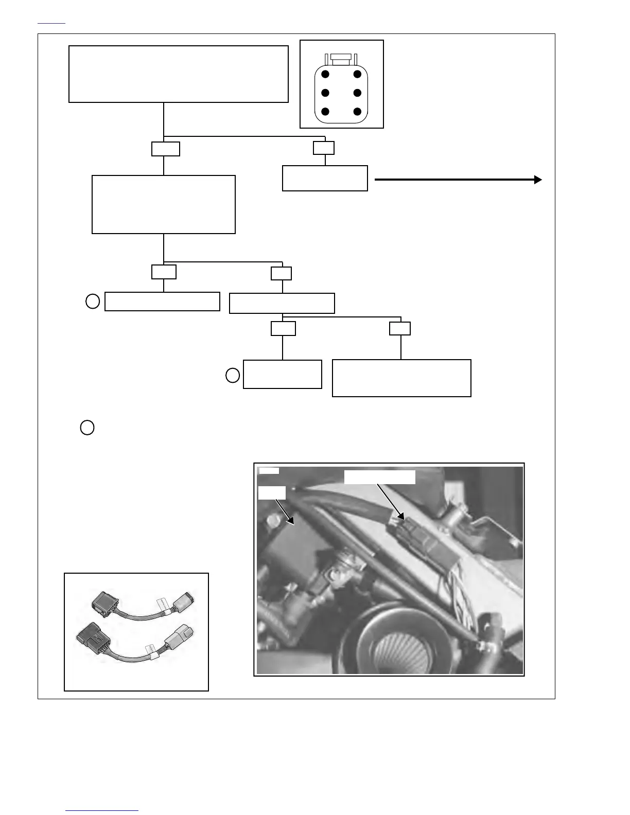
Figure 7-6. No Spark At Spark Plug
1
2
3
4
5
6
• Ignition On, Sidestand Up, transmission in Neutral
• Measure Voltage At Breakout Box- Multimeter Red
Lead To LT GN/GY (Pin 5) (+) and Black Lead To
BK (Pin 6) (-).
Is voltage 0.6-0.8 VDC?.
YES
NO
Go to Next Page.
Begin at top.
Remove Timer Cover (See Igni-
tion Module/Cam Position Sensor
for procedure).
Crank Engine.
Is LED Flashing?
NO
Is Rotor Cup Rotating?
Replace Ignition Module.
YES
YES
NO
Replace Ignition
Module.
Remove Gearcase Cover.
Inspect For Mechanical Failure.
Repair.
5009
5009
5005
Harness Adapters (HD-42962)
NOTE
Male connectors are labeled “A”
Female connectors are labeled “B”
3
3
Inspect ignition module for signs
of physical contact with rotor cup.
Replace rotor cup if necessary.
3
Connector [10]
Coil
7793
[10]