7-20 2002 Buell P3: Electrical
HOME
INSTALLATION
1. With the lipped side facing inboard, install new camshaft
oil seal into gearcase cover, if removed. Press seal into
position until lightly bottomed.
2. Install rotor cup.
a. Apply LOCTITE THREADLOCKER 243 (blue) to
threads of screw.
b. Position rotor cup onto end of camshaft aligning
notch with camshaft slot.
c. Install screw to secure rotor cup. Tighten screw to
43-53 in-lbs (5-6 Nm).
3. Install module plate with two screws.
4. Install ignition module wiring terminals into correct posi-
tions in plug end of connector [10]. See Wiring Diagram.
Install pin terminals. See B.2 DEUTSCH ELECTRICAL
CONNECTORS.
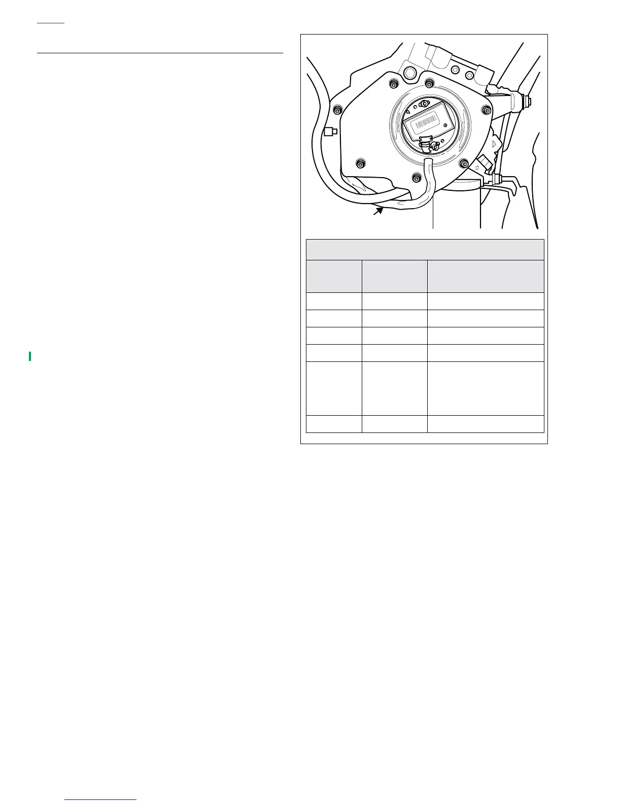
5. See Figure 7-17. Mate connector [10] and install to T-
stud on frame backbone.
6. Install locknut to clamp that secures hoses and wire har-
ness on right side of motorcycle.
7. Install module plate with two screws. Do not tighten
screws.
8. Install negative battery cable to battery terminal. Tighten
fastener to 60-96 in-lbs (7-11 Nm).
9. Check ignition timing. See IGNITION TIMING.
10. Tighten module plate screws to 10-20 in-lbs (1-2 Nm).
11. Install new outer timer cover.
Figure 7-20. Ignition Connector [10]
IGNITION MODULE CONNECTOR [10]
CHAMBER
NUMBER
WIRE COLOR FUNCTION
1White/Black To Ignition Switch
2Violet/White To TP Sensor
3Violet/Orange To Auto-Enrichener
4PinkTo Coil
5
*Lt Green/
Grey [10A]
*Tan/Yellow
[10B]
To Sidestand Interlock
6Black Ground
Wire Harness
to Connector [10]
a0288x7x