126
Connection of an External Initiator
→ Assemble the connection cables according to the general rules of technology.
→ Insertcablesthroughthecablegland(connectiononright)intotheinteriorofthehousing.
→ Connect the wires to the connection terminals according to the pin assignment.
→ Close the housing following the instructions in chapter “8OpeningandClosingtheHousing”.
NOTE!
Ensure IP protection!
` To ensure IP protection, the union nuts of the cable glands must be tightened in accordance with the
cablesizesordummyplugsused(approx.1.5Nm).
` If no external initiator is used, the right-hand connection opening must be tightly sealed using a dummy
plugorusingacablegland(SW19,Ø3-6mm)+dummyplug(Ø5-6mm)!
Use of the control head in a potentially explosive atmosphere
` Onlyusecablesandcableglandswhichareapprovedfortherespectiveapplicationareaandtthe
cable glands according to the respective operating instructions!
` Close all unnecessary openings with lock screws/plugs approved for explosions area!
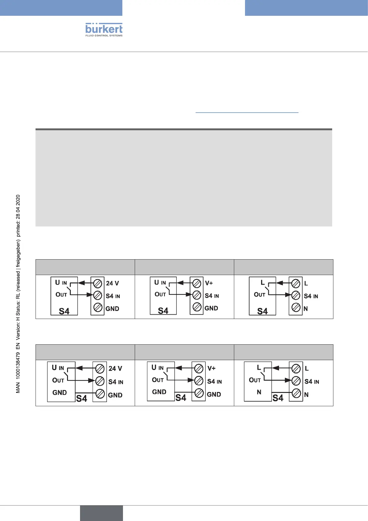
Connecting a 2-wire initiator:
24 V DC, AS-i
DeviceNet, IO-Link,
büS/CANopen
120 V AC
Connecting a 3-wire initiator:
24 V DC, AS-i
DeviceNet, IO-Link,
büS/CANopen
120 V AC
english
Control Head Type 8681