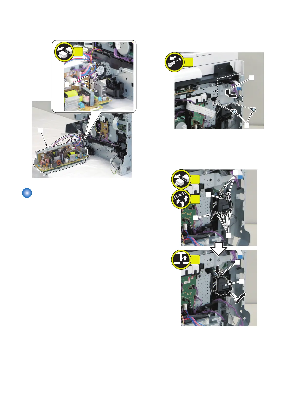
5. Remove the Low Voltage Unit [1]
• 3 connectors [2]
Removing the Fixing Sub PCB
■ Preparation
1. Removing the Right Cover.(Refer to “Removing the
Right Cover” on page 120)
2. Removing the Controller Cover.(Refer to “Removing
the Controller Cover” on page 157)
3. Removing the Wireless LAN PCB.(MF728Cdw /
727Cdw / 724Cdw only) (Refer to “Removing the
Wireless LAN PCB (MF728Cdw / 727Cdw / 724Cdw)”
on page 157)
4. Removing the Main Controller PCB.(Refer to
“Removing the Main Controller PCB” on page 157)
5. Removing the Main Controller Support Plate.(Refer
to “Removing the Main Controller Support Plate” on
page 161)
6. Removing the FAX PCB.(MF728Cdw / 727Cdw /
725Cdn only) (Refer to “Removing the FAX PCB
(MF728Cdw / 727Cdw / 725Cdw)” on page 171)
7. Removing the Fixing/Fixing Power Supply Cooling
Fan Unit.(Refer to “Removing the Fixing/Fixing
Power Supply Cooling Fan Unit” on page 180)
■ Procedure
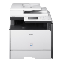
1. Remove the PCB Fixation Plate [1] (FAX model only).
• 2 Screws [2]
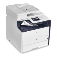
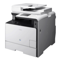
2. Remove the wire harness [1], and remove the wire
harness guide [2].
• 3 connectors [3]
• 4 fixing guides [4]
• 1 claw [5]
4. Disassembly/Assembly
166