Removing the Off Hook PCB
(MF728Cdw / 727Cdw / 725Cdn)
■ Preparation
1. Removing the Right Cover.(Refer to “Removing the
Right Cover” on page 120)
2. Removing the Left Cover.(Refer to “Removing the
Left Cover” on page 118)
3. Removing the Right Front Cover.(Refer to
“Removing the Right Front Cover” on page 121)
4. Removing the ADF Unit + Reader Unit.(Refer to
“Removing the ADF Unit + Reader Unit” on page
130)
5. Removing the Rear Upper Cover.(Refer to
“Removing the Rear Upper Cover” on page 123)
6. Removing the Upper Cover.(Refer to “Removing the
Upper Cover” on page 125)
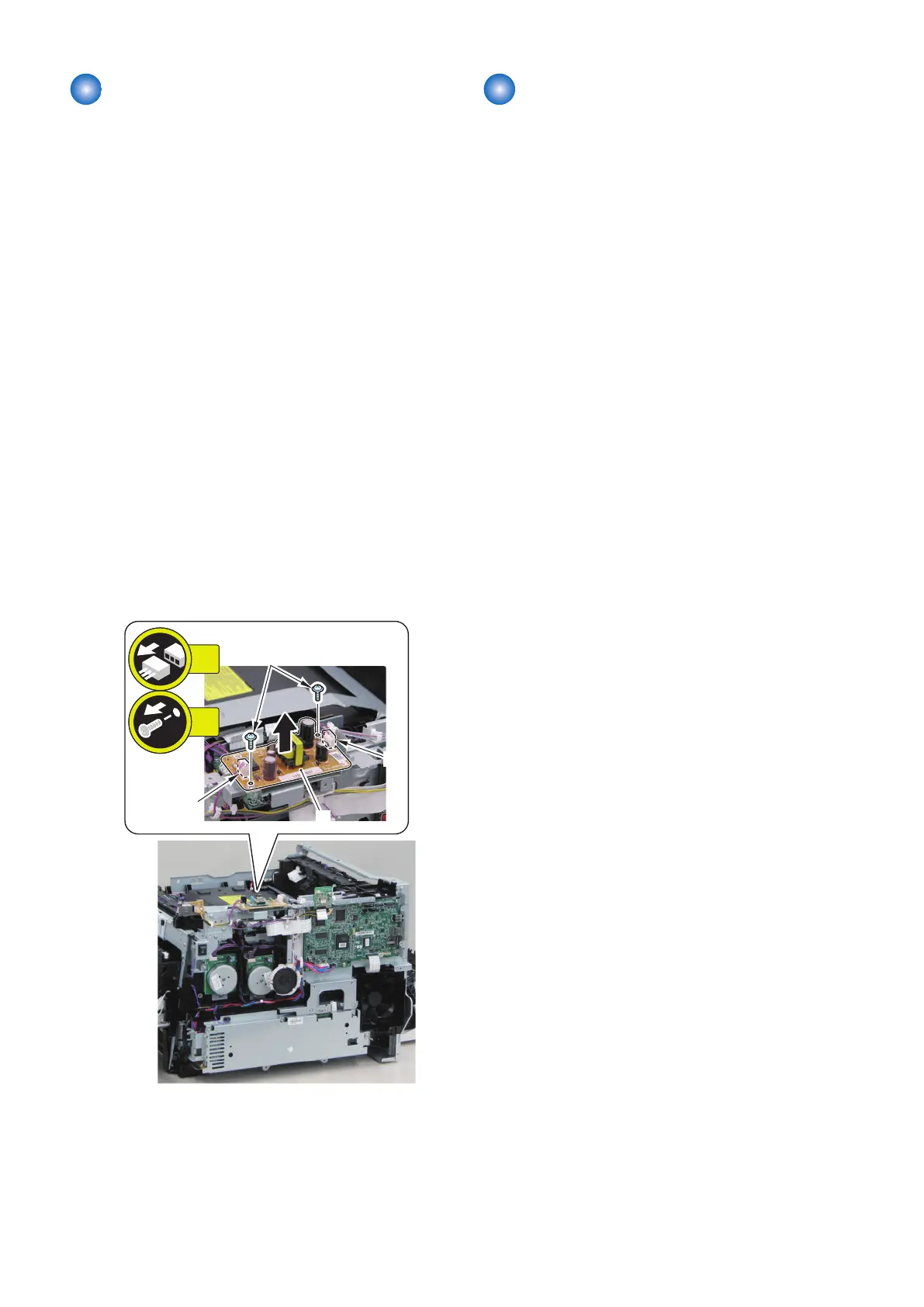
■ Procedure
1. Remove the Off Hook PCB [1].
• 2 Connector [2]
• 2 Screws [3]
Removing the Main Drive Unit
■ Preparation
1. Removing the Right Cover.(Refer to “Removing the
Right Cover” on page 120)
2. Removing the Left Cover.(Refer to “Removing the
Left Cover” on page 118)
3. Removing the Right Front Cover.(Refer to
“Removing the Right Front Cover” on page 121)
4. Removing the ADF Unit + Reader Unit.(Refer to
“Removing the ADF Unit + Reader Unit” on page
130)
5. Removing the Rear Upper Cover.(Refer to
“Removing the Rear Upper Cover” on page 123)
6. Removing the Upper Cover.(Refer to “Removing the
Upper Cover” on page 125)
7. Removing the Wireless LAN PCB.(MF728Cdw /
727Cdw / 724Cdw only) (Refer to “Removing the
Wireless LAN PCB (MF728Cdw / 727Cdw / 724Cdw)”
on page 157)
8. Removing the Main Controller PCB.(Refer to
“Removing the Main Controller PCB” on page 157)
9. Removing the Main Controller Support Plate.(Refer
to “Removing the Main Controller Support Plate” on
page 161)
10. Removing the Drum Motor.(Refer to “Removing the
Drum Motor” on page 196)
11. Removing the Developing Motor.(Refer to
“Removing the Developing Motor” on page 195)
12. Removing the Driver PCB.(Refer to “Removing the
Driver PCB” on page 167)
13. Removing the FAX PCB.(MF728Cdw / 727Cdw /
725Cdn only) (Refer to “Removing the FAX PCB
(MF728Cdw / 727Cdw / 725Cdw)” on page 171)
14. Removing the Fixing/Fixing Power Supply Cooling
Fan Unit.(Refer to “Removing the Fixing/Fixing
Power Supply Cooling Fan Unit” on page 180)
15. Removing the Fixing Sub PCB.(Refer to “Removing
the Fixing Sub PCB” on page 166)
16. Removing the Fixing Motor Unit.(Refer to
“Removing the Fixing Motor Unit” on page 205)
17. Removing the Low Voltage Unit.(Refer to “Removing
the Low Voltage Unit” on page 165)
18. Removing the DC Controller PCB.(Refer to
“Removing the DC Controller PCB” on page 162)
19. Removing the Relay PCB.(Refer to “Removing the
Relay PCB” on page 168)
4. Disassembly/Assembly
172