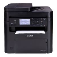
9. Remove the spring [1] and the Fixing Film Unit [2].
• 2 Hooks [3]
• Harness Guide [A]
CAUTION:
Be careful not to lose the spring because the spring is
small.
Removing the Fixing Pressure
Roller
■ Preparation
1. Removing the Right Cover.(Refer to “Removing the
Right Cover” on page 120)
2. Removing the Left Cover.(Refer to “Removing the
Left Cover” on page 118 )
3. Removing the Rear Upper Cover.(Refer to
“Removing the Rear Upper Cover” on page 123)
4. Removing the Rear Cover.(Refer to “Removing the
Rear Cover” on page 123)
5. Removing the Rear Lower Cover.(Refer to
“Removing the Rear Lower Cover” on page 123)
6. Removing the Rear Cover Rib Unit.(Refer to
“Removing the Rear Cover Rib Unit” on page 125 )
7. Removing the Duplex Printing Reverse Drive Unit.
(Refer to “Removing the Duplex Reverse Drive Unit”
on page 179)
8. Removing the Fixing Assembly.(Refer to “Removing
the Fixing Assembly” on page 200)
9. Removing the Fixing Film Unit.(Refer to “Removing
the Fixing Film Unit” on page 201)
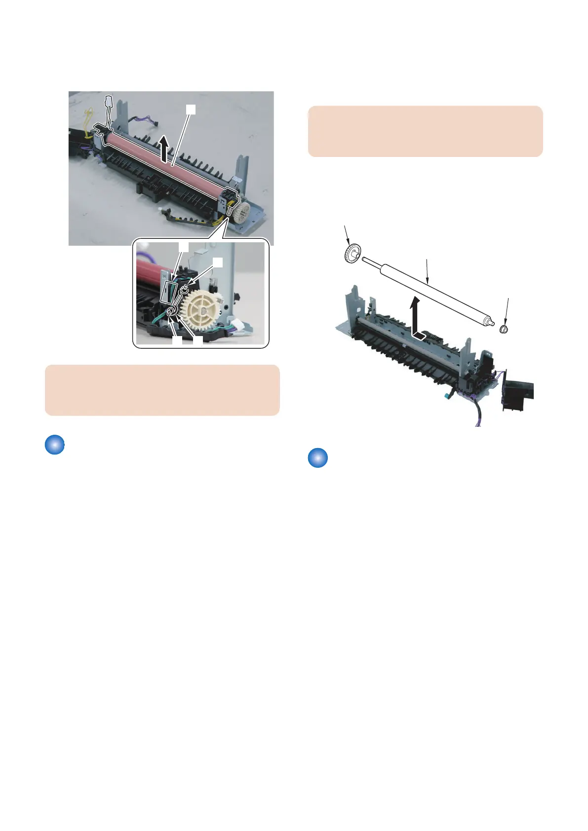
■ Procedure
CAUTION:
Be sure not to touch the surface of the Fixing Pressure
Roller.
1. Remove the Fixing Pressure Roller [1].
• 2 Bushings [2]
• 1 Gear [3]
Removing the Fixing Motor
Unit
■ Preparation
1. Removing the Right Cover.(Refer to “Removing the
Right Cover” on page 120)
2. Removing the Controller Cover.(Refer to “Removing
the Controller Cover” on page 157)
3. Removing the Wireless LAN PCB.(MF728Cdw /
727Cdw / 724Cdw only) (Refer to “Removing the
Wireless LAN PCB (MF728Cdw / 727Cdw / 724Cdw)”
on page 157)
4. Removing the Main Controller PCB.(Refer to
“Removing the Main Controller PCB” on page 157)
5. Removing the Main Controller Support Plate.(Refer
to “Removing the Main Controller Support Plate” on
page 161)
6. Removing the FAX PCB.(MF728Cdw / 727Cdw /
725Cdn only) (Refer to “Removing the FAX PCB
(MF728Cdw / 727Cdw / 725Cdw)” on page 171)
4. Disassembly/Assembly
205
 Loading...