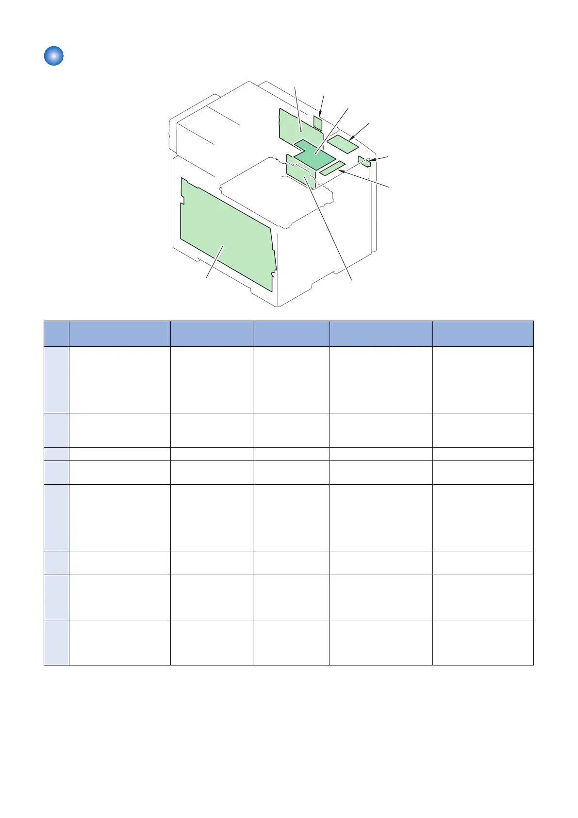
PCB
UN3
UN5
UN15
UN17
UN1
UN4
UN13
UN23
No. Parts Name Main Unit Remarks Reference Adjastment during
parts replacement
UN1 DC Controller PCB Product configuration - “Removing the DC Control-
ler PCB” on page 162
“Before Replacing the DC
Controller PCB” on page
162
“After Replacing the DC
Controller PCB” on page
163
UN3 High Voltage Power Sup-
ply PCB
Product configuration - “Removing the High Volt-
age Power Supply PCB” on
page 163
-
UN4 Laser Driver PCB Laser Scanner Unit - - -
UN5 Relay PCB Product configuration - “Removing the Relay PCB”
on page 168
-
UN1
3
Main Controller PCB Product configuration - “Removing the Main Con-
troller PCB” on page 157
“Before Replacing the
Main Controller PCB” on
page 157
“After Replacing the Main
Controller PCB” on page
159
UN1
5
USB Host PCB Product configuration - - -
UN1
7
Off Hook PCB Product configuration MF728Cdw /
727Cdw / 726Cdw /
725Cdn
“Removing the Off Hook
PCB (MF728Cdw /
727Cdw / 725Cdn)” on
page 172
-
UN2
3
Wireless LAN PCB Product configuration MF728Cdw /
727Cdw / 726Cdw /
724Cdw
“Removing the Wireless
LAN PCB (MF728Cdw /
727Cdw / 724Cdw)” on
page 157
-
4. Disassembly/Assembly
106



 To Next Page