■ Procedure
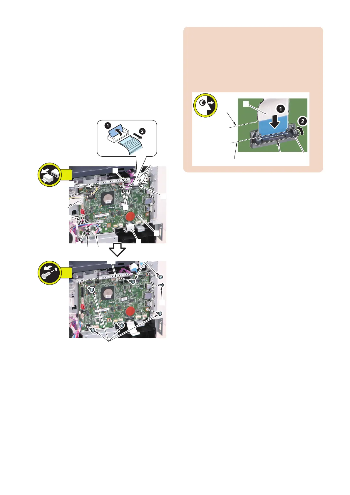
1. Remove the Main Controller PCB [1].
• 1 Flat Cable Connector Lock [2]
• 3 Flat Cables [3]
• 1 Flat Cable [4] (FAX model only)
• 6 Connectors [5]
• 2 Connectors [6] (FAX model only)
• 1 Connector [7] (MF728Cdw / 724Cdw only)
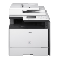
• 6 Screws [8] (TP)
• 1 Screw [9] (Binding)
• 1 Hook [10]
[5]
[5]
[6]
[4]
[1]
[3]
[3]
[5]
[8]
[8]
[2]
7x
13x
[5]
[5][7]
[9]
[10]
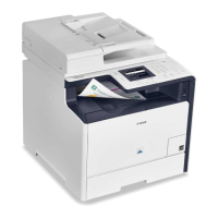
CAUTION:
When connecting the Flat Cable, be sure to perform
the following; while pushing the Flat Cable [1] against
the connector with a lock [2], check that the line on the
edge [A] of the Flat Cable Connector and the line on
the edge [B] of the Flat Cable Connector Lock are
parallel, and then close the Flat Cable Connector Lock
[3].
■ After Replacing the Main Controller
PCB
1. Setting of destination/paper size group
1. COPIER > OPTION > BODY > LOCALE (to set
destination groups)
[Settings]
1: Japan, 2: North America, 3: Korea, 4: China, 5:
Taiwan, 6: Europe, 7: Asia, 8: Oceania
2. COPIER > OPTION > BODY > SIZE-LC (to set
paper size groups)
[Settings]
1: AB series, 2: Inch series, 3: A series, 4: AB/Inch
series
2. Executing initial settings.
Perform the following procedure to change the settings
back to the initial settings.
1. Execute the following service mode to initialize the
data according to the setting values in step 1.
COPIER > FUNCTION > CLEAR > ALL (to clear all
data)
• Setting / Registration data (the default value
for each destination is set).
• Service mode data (the default value for each
destination is set).
• Job IDs
• Log data
• Dates
2. Execute the following service mode to clear the
reader/DF-related factory adjustment values.
COPIER > FUNCTION > CLEAR > R-CON
4. Disassembly/Assembly
159