Basic Configuration
Configuration function
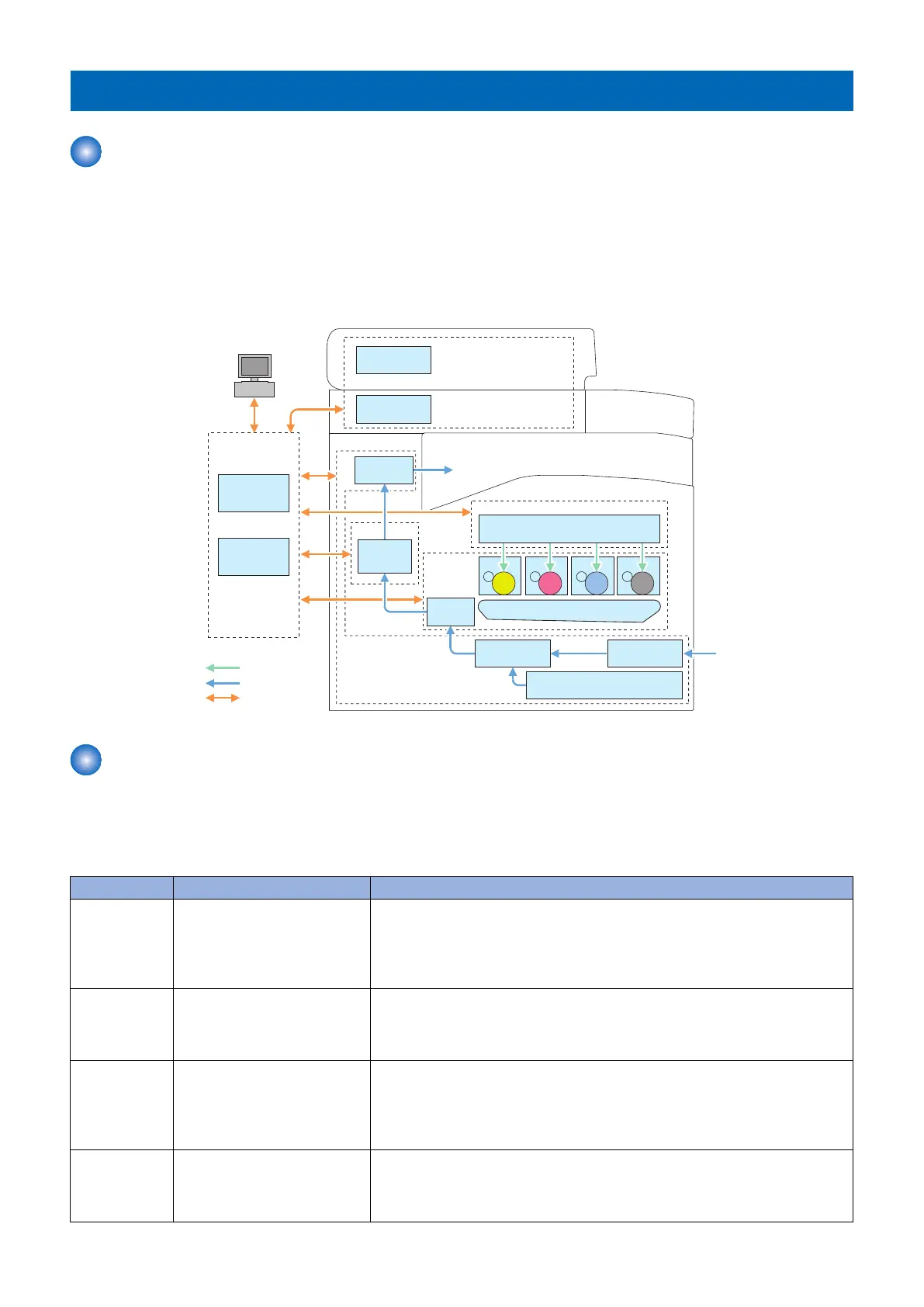
This device is roughly composed of the 6 functional blocks as shown in the figure below
• Document exposure/delivery system
• Controller system
• Laser exposure system
• Image formation system
• Fixing system
• Pickup / Feed System
Laser Scanner
Laser Exposure System
Main
Controller
DC
Controller
Controller System
Laser beam
㻼㼍㼜㼑㼞㻌㼒㼘㼛㼣
Signal flow
ITB Unit
Secondary
Transfer
Image
Formation
System
Cassette
Manual Feed
Pickup Unit
Pickup
Unit
Pickup/feed System
Fixing
Assembly
Fixing System
Delivery
Assembly
CIS Unit
PC
ADF
Document Exposure/
Feeding System
Drum Drum Drum Drum
Basic Sequence
■ Basic Operational Sequence
The CPU on the DC controller PCB controls the operational sequence. The table below shows the operation and the purposes
in each status from start-up of the device and to last rotation after print job completion.
Section Outline Operation
WAIT
(Wait)
Interval from power-ON or reac-
tivation from sleep mode upon
shutting the door(s) to entering
the print-ready status
Activate the printer to be ready for printing. During WAIT time, the following oper-
ations are done: pressure is applied to the pressure roller of the fixing assembly;
check cartridges and units being in place; move the developing unit to the home
position; and, clean the ITB. When needed, color displacement is corrected and the
image is stabilized.
STBY
(STBY)
Interval from the wait time or the
last rotation to issuance of a print
command from the main control-
ler or power-OFF.
Maintain the print-ready status. The printer enters the sleep mode upon receiving
a “sleep” command from the main controller during the stand-by status. The printer
executes color displacement correction or image stabilization upon receiving cor-
responding commands from the main controller.
INTR
(IINTR)
Interval from issuance of a print
command from the main control-
ler during the stand-by status to
warming up the fixing assembly
to the target temperature.
To make the printer ready for print jobs, activate high-voltage bias PCBs, the laser
scanner unit and the fixing assembly.
PRINT
(Print)
Interval from the initial rotation to
completion of last page fixation.
Based on the video signals input from the main controller, form the static latent
image on the photosensitive drum to transfer and fix the toner image on paper.
When a certain pages are printed after power-ON, the device undergoes color dis-
placement correction and/or image stabilization.
2. Technical Explanation
20