Controller System
Disassembly/Assembly
Procedure
Removing the Controller
Cover
■ Preparation
1. Removing the Right Cover.(Refer to “Removing the
Right Cover” on page 120)
■ Procedure
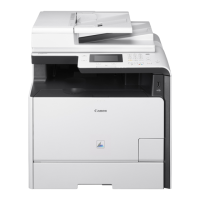
1. Remove the Controller Cover [1].
• 9 Screws [2]
• 2 Hooks [3]
Removing the Wireless LAN
PCB (MF728Cdw / 727Cdw /
724Cdw)
■ Preparation
1. Removing the Right Cover.(Refer to “Removing the
Right Cover” on page 120)
2. Removing the Controller Cover.(Refer to “Removing
the Controller Cover” on page 157)
■ Procedure
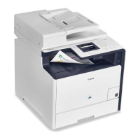
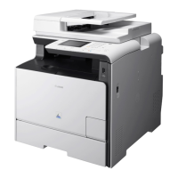
1. Remove the Wireless LAN PCB [1].
• 1 Screw [2]
• 1 Flat Cable [3]
Removing the Main Controller
PCB
CAUTION:
When replacing the Main Controller PCB, be sure to
perform the works to be done before replacing the Main
Controller PCB (Refer to “Before Replacing the Main
Controller PCB” on page 157) and the works be done
after replacing the Main Controller PCB (Refer to “After
Replacing the Main Controller PCB” on page 159).
■ Before Replacing the Main
Controller PCB
Back up user data (settings, registered data, etc.) and service
mode data for setting and registration after PCB replacement.
Take notes if data is unable to back up.
4. Disassembly/Assembly
157