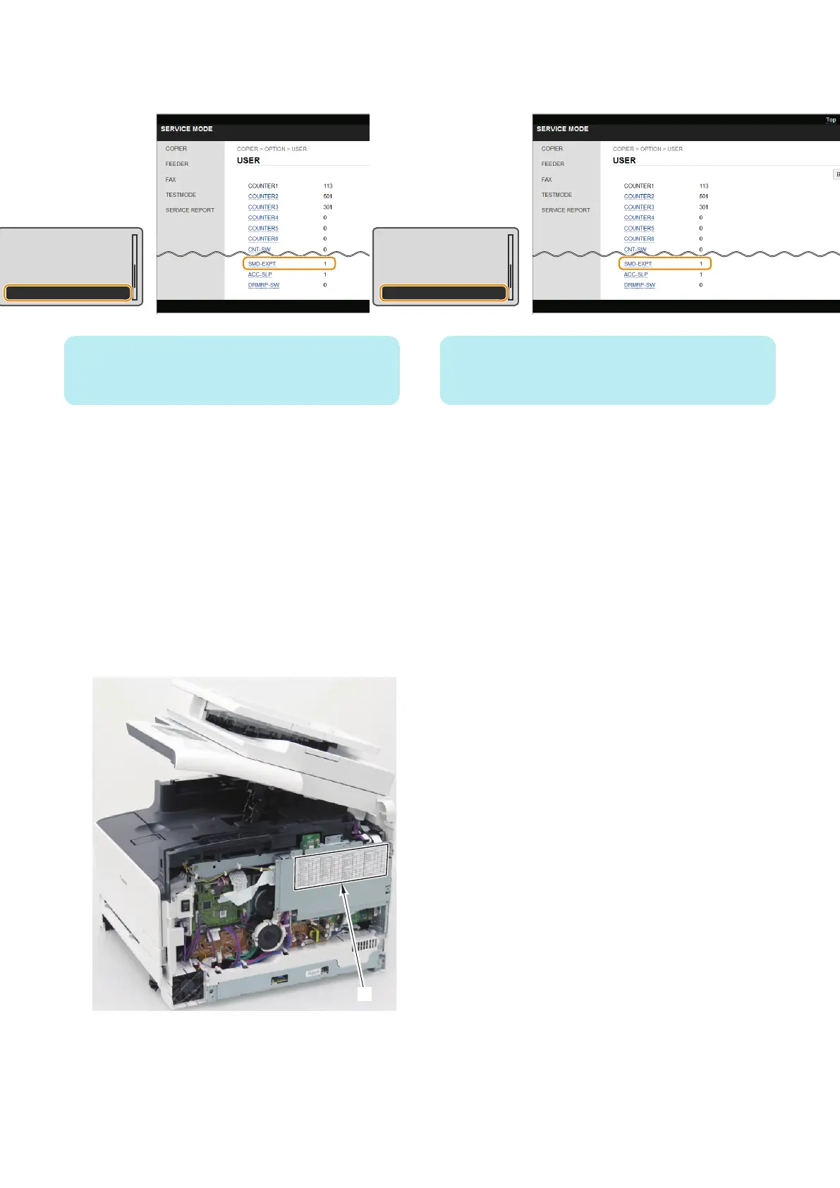
1. Enter service mode, and set the following item to "1".
• COPIER > OPTION > USER > SMD-EXPT
TNRB-SW : 0
SCALL-SW : 0
SCALLCMP : 0
PC-MODE : 0
SMD-EXPT : 1
NOTE:
The [SMD-EXPT] setting can be specified either from the
Control Panel or from the remote UI.
2. Using the DCM function (Refer to “Setting
Information Export/Import Function (DCM)” on page
58), export the following information.
• User data (the settings of the [Settings/
Registration] menu and the address book)
• Service mode setting information
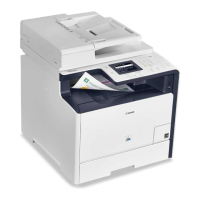
3. Write down the following information because these
settings need to be configured (entered) after
replacing the PCB.
• The default settings shown on the service label [1]
• The machine's serial number
• Settings/Registration > System Settings > Device
Information> Location
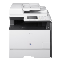
4. Enter service mode, and set the following item to "0".
• COPIER > OPTION > USER > SMD-EXPT
TNRB-SW : 0
SCALL-SW : 0
SCALLCMP : 0
PC-MODE : 0
SMD-EXPT : 1
NOTE:
The [SMD-EXPT] setting can be specified either from the
Control Panel or from the remote UI.
■ Preparation
1. Removing the Right Cover.(Refer to “Removing the
Right Cover” on page 120)
2. Removing the Controller Cover.(Refer to “Removing
the Controller Cover” on page 157)
3. Removing the Wireless LAN PCB.(MF728Cdw /
727Cdw / 724Cdw only) (Refer to “Removing the
Wireless LAN PCB (MF728Cdw / 727Cdw / 724Cdw)”
on page 157)
4. Disassembly/Assembly
158