THS – FI022GB2K8v3 --- V - MAINTENANCE
18
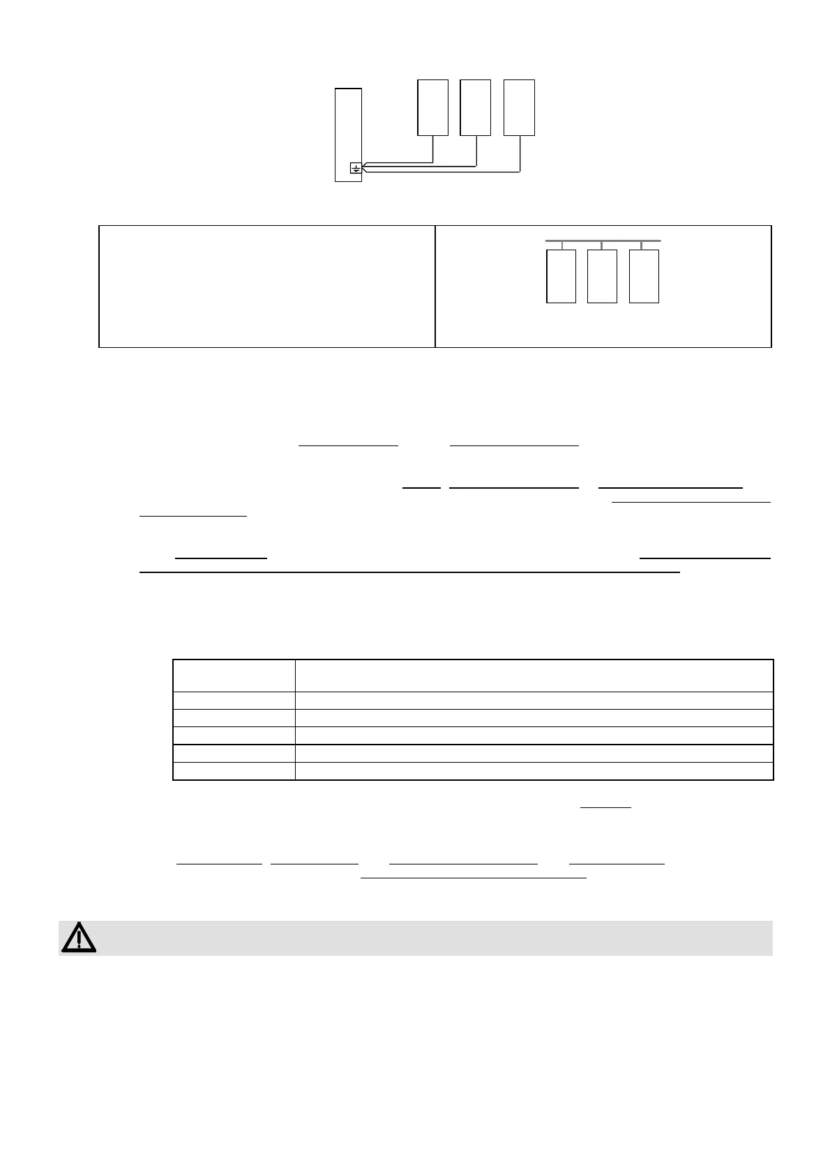
M1 MD M2
QE
Fig.II-4. QE: electrical board; M1: machine 1; M2: machine 2; MD: metal detector.
• Warning! If metal ducts are used for production line
power and control lines, it is advisable not to create an
electrical connection between the conveyor belt frame
and other nearby devices through the same ducts: if this
is done, interference due to multiple ground returns
could be produced.
M1 MD M2
ci
Fig. II-5. ci: ducts in insulating material; M1: machine 1; M2:
machine 2; MD: metal detector
• Impulsive sources. In general, impulsive sources
must be distanced or eliminated.
It is therefore recommended that, during installation, the following procedures be carried out:
1 position as far as possible from the probe any motors
, electrical power boards or electromagnetic actuators (it is
recommended that they be replaced with similar pneumatic devices); position fluorescent lights and their
respective reactors at a distance from the metal detector probe; where possible replace fluorescent lights with
filament lights.
2 equip electrical motors with special iron screens and mains filters of sufficient capacity. It is recommended that
motors running on alternating current be used as opposed to those running on direct current. The table that
follows provides some general guidelines for the distances to be placed between the probe and asynchronous
motors, depending on their power.
Table II-A
Recommended minimum distance between the probe and motors with alternating current
(without screening of the motor)
Power Minimum distance
THS/M & THS/A Other THS models
0,5 CV 5 x DH 3 x DH
1 CV 6 x DH 4 x DH
2 CV 8 x DH 5 x DH
3 CV 10 x DH 6 x DH
> 20 CV 15 x DH ( >10 x DH if screened) 10 x DH ( 6 x DH if screened)
2.1 In the immediate proximity of the metal detector, the motors may be screened by means of cylindrical
enveloping in iron; such cylinders must have a sufficiently large diameter in order to contain the motors and
a thickness of not less than 2 mm. The cylinders must be of the unwelded type.
3 fit the electromagnets
, remote controls and continuous current motors with RC muffling nets (ask our technical
office for details of the dimensions) and braid the respective power supply cables
with as short a pitch as possible.
Fix the cable which connects the probe to the power supply unit so that it can not oscillate or vibrate.
If the cable is too long, DO NOT CUT THE CABLE: COIL UP THE EXCESS!
 Loading...